FC9000-UM-251-9370 7-30
7 DISASSEMBLY AND REASSEMBLY
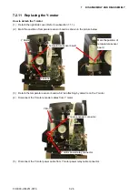
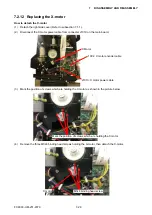
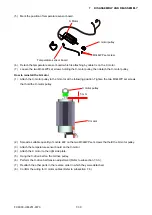
(5) Mark the position of temperature sensor board.
X Motor
Temperature sensor board
M3L4WP set screw
X motor pulley
(6) Detach the temperature sensor board which is attaching by cable tie on the X motor.
(7) Loosen the two M3L4WP set screws holding the X-motor pulley, then detach the X-motor pulley.
How to reinstall the X-motor
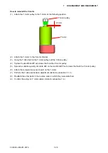
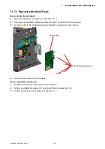
(1) Attach the X-motor pulley to the X-motor at the following position. Tighten the two M3L4WP set screws
that hold the X-motor pulley.
X motor
X motor pulley
5 mm
(2) Spread a suitable quantity of Loctite 222 on the two M3L4WP set screws that hold the X-motor pulley.
(3) Attach the temperature sensor board on the X-motor
(4) Attach the X motor to the right side plate.
(5) Hang the X-drive belt on the X-drive pulley.
(6) Perform the X-drive belt tension adjustment (Refer to subsection 7.3.3.).
(7) Reattach the other parts in the reverse order in which they were detached.
(8)
Confirm the wiring for X motor cables (Refer to subsection 7.4.).
Summary of Contents for FC9000-100
Page 1: ...CUTTING PLOTTER SERVICE MANUAL FC9000 75 100 140 160 FC9000 UM 251 01 9370...
Page 2: ......
Page 4: ...FC9000 UM 251 9370 II...
Page 38: ......
Page 201: ...FC9000 UM 251 9370 10 2 10 PARTS LIST Outer Casing 1 2 3 4 10 7 11 5 16 15 6 12 12 9 13 14 8...

