FC9000-UM-251-9370 IV
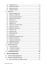
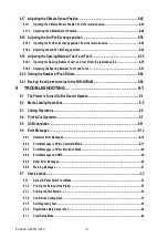
7.1.9 Replacing the Fan Cover ........................................................................................................................7-9
7.1.10 Replacing the Pen Block Cover ...........................................................................................................7-10
7.1.11 Replacing the Push Roller ...................................................................................................................7-11
7.1.12 Replacing the Cutting Mat ...................................................................................................................7-12
7.2.1 Replacing the Rear Media Sensor .......................................................................................................7-13
7.2.2 Replacing the Front Media Sensor ......................................................................................................7-13
7.2.3 Replacing the Registration Mark Sensor ............................................................................................7-14
7.2.4 Replacing the Control Panel Board.....................................................................................................7-16
7.2.5 Replacing the LCD ................................................................................................................................7-17
7.2.6 Replacing the Pen Block ......................................................................................................................7-18
7.2.7 Replacing the Y-belt .............................................................................................................................7-20
7.2.8 Replacing the Push Roller Sensor Board ...........................................................................................7-23
7.2.9 Replacing the Y-relay Board ................................................................................................................7-24
7.2.10 Replacing the Cam Sensor board .......................................................................................................7-25
7.2.11 Replacing the Y-motor ..........................................................................................................................7-26
7.2.12 Replacing the X-motor .........................................................................................................................7-29
7.2.13 Replacing the Main Board ....................................................................................................................7-31
7.2.14 Replacing the Fan .................................................................................................................................7-32
7.2.15 Replacing the Drive Roller Shaft Assembly .......................................................................................7-33
7.2.16 Replacing the Y Flexible Cable ............................................................................................................7-36
7.2.17 Replacing the Push Roller assembly ..................................................................................................7-38
7.2.18 Replacing the Push Roller base ..........................................................................................................7-41
7.2.19 Replacing Power Supply Board .......................................................................................................... 7-43
7.3.1 Y-Belt Tension Adjustment ................................................................................................................. 7-44
7.3.2 Y-Drive Belt Tension Adjustment ........................................................................................................7-47
7.3.3 X-Drive Belt Tension Adjustment ....................................................................................................... 7-48
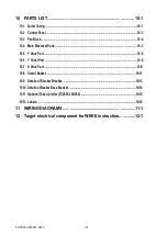
8 Electrical Adjustment ............................................................... 8-1
8.1 List of Items Requiring Readjustment ................................................................................ 8-1
8.2 Flowchart of the Adjustment Sequence.............................................................................. 8-2
Summary of Contents for FC9000-100
Page 1: ...CUTTING PLOTTER SERVICE MANUAL FC9000 75 100 140 160 FC9000 UM 251 01 9370...
Page 2: ......
Page 4: ...FC9000 UM 251 9370 II...
Page 38: ......
Page 201: ...FC9000 UM 251 9370 10 2 10 PARTS LIST Outer Casing 1 2 3 4 10 7 11 5 16 15 6 12 12 9 13 14 8...


