5-17
Chapter 5 Detailed Settings
6.
Measure by how much the registration mark for comparison is displaced from the registration mark for
correction.
Measure the distance between the center of each line.
In the case of the image on the bottom in Step 5, the correction needs to be made in the negative
direction for both X and Y so the correction values for each will be a negative value.
7.
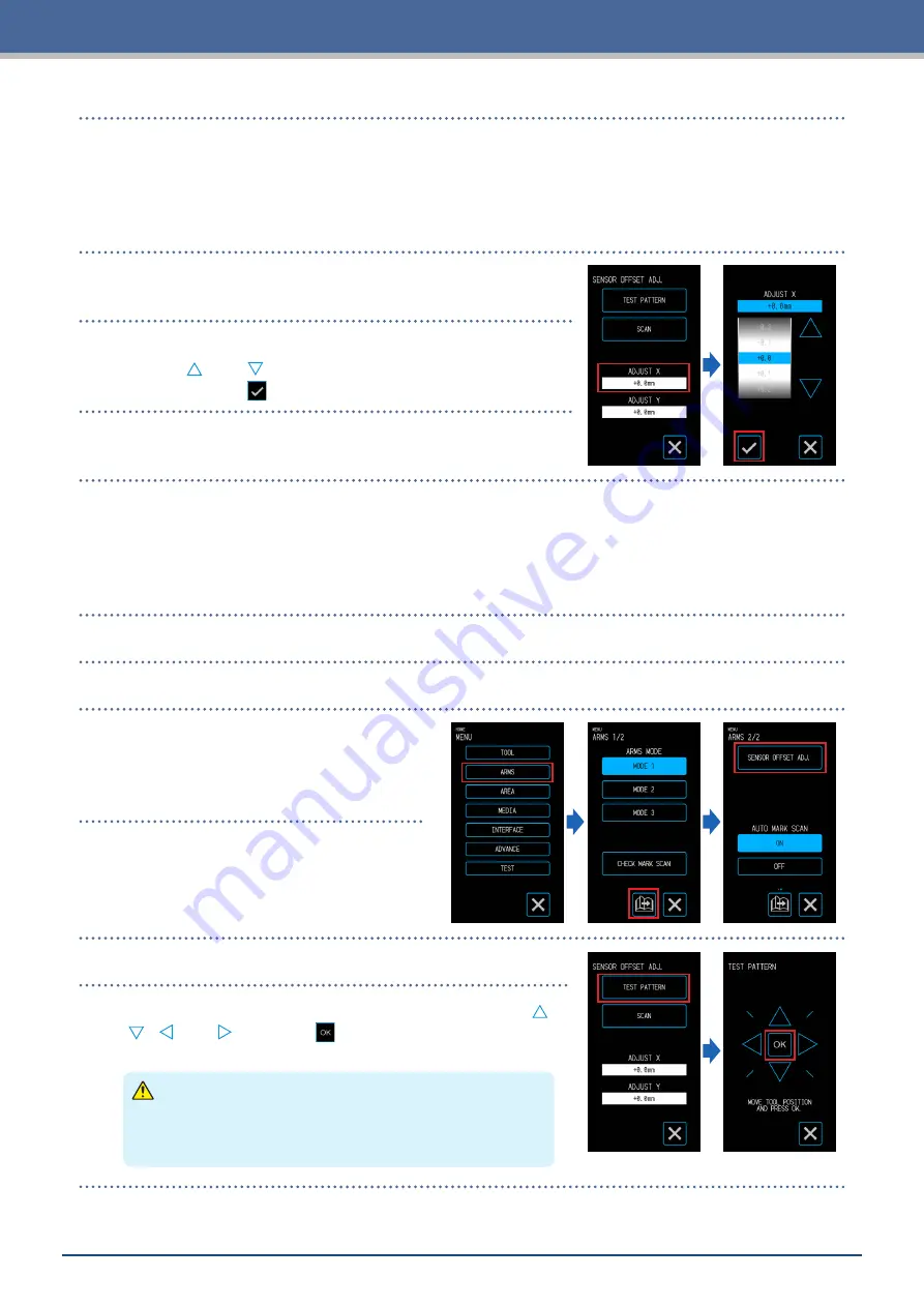
Touch the "ADJUST X".
8.
Input the value of X measured in Step 5.
Use the "
" and "
" to select the setting value and confirm the
selection with the
(Confirm).
9.
Similarly input "ADJUST Y".
Adjusting after Cutting the Test Pattern (Registration Mark for Correction)
Plot a registration mark for adjustment of the registration mark position and make the adjustment using this
registration mark.
1.
Load white media for cutting.
2.
Set a drawing pen in the tool holder and select a CONDITION NO.
3.
From the "MENU" screen, open the "ARMS
2/2" screen.
4.
Touch the "SENSOR OFFSET ADJ.".
5.
Touch the "TEST PATTERN".
6.
Move to the registration mark cutting position by using the "
"
" " " " and "
". When the
(OK) is touched, the registration
mark for correction will be plotted.
CAUTION
When the "OK" is touched, the media and pen carriage will
start moving. Be careful to avoid contact with your body or any
object.
Summary of Contents for CELITE-50
Page 1: ...USER S MANUAL CE LITE 50 UM 151...
Page 2: ......
Page 10: ......
Page 22: ......
Page 78: ......
Page 101: ...5 23 Chapter 5 Detailed Settings 3 Select ON or OFF for WIDTH DETECTION...
Page 112: ......
Page 116: ...A 4 Appendix A 3 Appearance Drawing 164 784 227 173 400 Units mm Dimension error 5 mm...
Page 118: ...A 6 Appendix 3 PIECES Previous Page HOME SELECT FILE...
Page 119: ...A 7 Appendix TOOL ARMS MODE 1 MODE 2 MODE 3 CHECK MARK SCAN SENSOR OFFSET ADJ Next Page MENU...
Page 120: ...A 8 Appendix INTERFACE ADVANCE TEST Previous Page AREA MEDIA MENU...
Page 127: ......
Page 128: ......


