© Gebr.Graef Mai 2002
Technische Änderungen vorbehalten
42
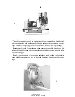
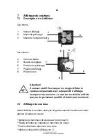
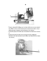
* Set the adjusting wheel of the sharpening unit to 1 (grinding) and switch on
the machine. The grinding process starts. The duration of the grinding ac-
tion depends on the condition of the knife.
* If a burr has formed at the knife blade, turn the adjusting wheel to position
2 (deburring). Permit the machine to run for some revolutions until no burr
can be seen.
* Use the red off button to switch the machine off after the grinding process.
* Set the adjusting wheel of the sharpening unit to 0 position. Open the stop
and pull the carriage back. Remove the sharpening unit.
* Clean the machine and the knife (chapter 5).
7.3
Changing the knife
Warning !
Sharp knife ! May cause severe cut injuries also when
it is not running. The knife may be changed by trained
expert staff only.
Important !
The knife has to be changed when the spacing be
tween the knife blade and motor exceeds 6 mm.
8
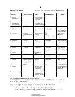
Fault finding
Fault
Cause
Solution
carriage is stiff
carriage slide / carriage
grease carriage slide /
rod are dry
carriage rod (chapter 6)
end piece holder is stiff
end piece holder rod is dry
grease holder rod
(chapter 6)
carriage cannot be
carriage lock is
close stop
tilted
blocked
bad cut
knife is blunt
sharpen knife (7)
bad sharpening result
grinding discs are greasey
replace drinding disc
knife cannot be sharpened
more than the permissible
replace knife
5 mm have been ground
55
3
Transport, installation
3.1
Transport
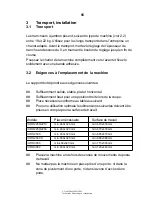
Les trancheurs à jambon pèsent, suivant le type de machine (voir 2.2)
entre 18 et 22 kg. Utilisez pour les longs transports dans l’entreprise un
chariot adapté. Avant le transport, mettez le réglage de l’épaisseur de
tranche en dessous du 0, en tournant le bouton de réglage jusqu’en fin de
course.
Poussez le chariot de la machine complètement vers l’avant et fixez le
solidement avec une bande adhésive.
3.2
Exigences à l’emplacement de la machine
Le support doit répondre aux exigences suivantes:
##
Suffisamment solide, stable, plat et horizontal.
##
Suffisamment haut pour une position droite lors de la coupe.
##
Place nécessaire conforme au tableau suivant:
##
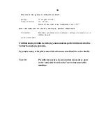
Pour une utilisation optimale les dimensions suivantes doivent être
prises en compte pour la surface de travail:
Modèle
Place nécessaire
Surface de travail
EURO 2200/2210
min. 460x320 mm
min. 670x430 mm
EURO 2250/2260
min. 460x320 mm
min. 670x470 mm
EURO 2500
min. 460x320 mm
min. 685x470 mm
EURO 2560 S
min. 460x320 mm
min. 680x380 mm
EURO 3000
min.460x320 mm
min. 715x500 mm
EURO 3060
min. 460x320 mm
min. 720x440 mm
##
Placez la machine en dehors des zones de mouvements du poste
de travail.
##
Ne mettez pas la machine en place près d’une porte: ni dans la
zone de pivotement d’une porte, ni dans la zone d’accès d’une
porte.
Summary of Contents for EURO 2200
Page 21: ... Gebr Graef Mai 2002 Technische Änderungen vorbehalten 21 ...
Page 44: ...44 ...
Page 67: ... Gebr Graef Mai 2002 Technische Änderungen vorbehalten 67 ...
Page 90: ...90 ...

