Operation
309028ZAT
29
Initial System Startup Procedure
Settings for Initial System Startup
The initial system startup procedure contains the
checklist of settings, adjustments, and procedural steps
that must be completed before the system is ready for
daily operation.
NOTE:
Complete the startup procedure for the LH
Supply Unit (A) first. Then, repeat the startup procedure
for the RH Supply Unit (B).
Perform the initial system startup procedure as follows:
1. Check all material hoses and fittings to ensure
tightness and to prevent any material leakage.
2. Check all system air lines. Make sure that all routing
of air lines will not interfere with any moving
components within the system.
3. Fill the packing nut/wet cup on both Pumps 1/3 full
with Graco throat seal liquid (p/n 206995). Refer to
instruction manual 308147 or 308148 for details.
4. Open the Main Air Shutoff Valve (P), making air
pressure available to the unit. See F
. 10 on page
25.
5. At the Pneumatic Logic Panel (G), open the Panel
Air Inlet Valve (AH), making air pressure available to
the Pneumatic Logic Panel. See F
6. Adjust both Pump main air regulators (AC, AE) to 0
psi.
7. FOLLOWER VENT Directional Valve (AD) switch
should be in AUTO position.
8. Set the RAM POSITION Switch (AG) to RAISE.
9. Press the RAM UP Pushbutton (AF) to raise the
Follower Plate (D) above the height of the material
drum to be used.
10. Set the RAM POSITION Switch (AG) to
HOLD/NEUTRAL.
Adjusting the Pump Regulators
NOTE:
Both Pumps must operate at the same cycles
per minute rate to prevent the occurrence of uneven
drum evacuation.
NOTE:
For the maximum air input pressure for each
Pump, see the appropriate manual shown in
11. Run the system under normal conditions. Adjust the
PUMP NO. 1 REGULATOR Control Knob (AC) to
the desired setting as follows:
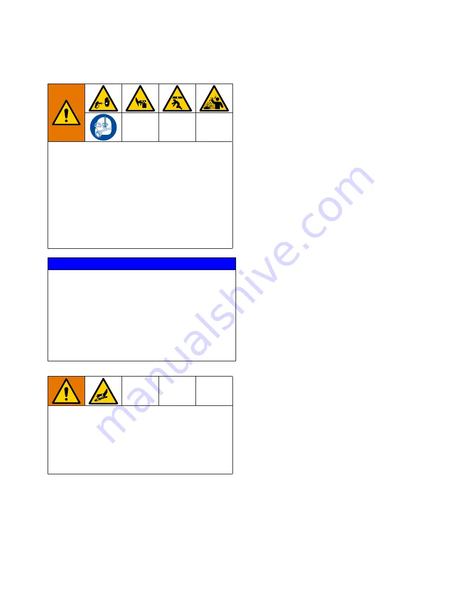
To reduce the risk of serious bodily injury, such as
skin injection or splashing fluid in the eyes or on the
skin, always wear eye protection and protective
clothing when installing, operating, or servicing this
equipment.
Moving equipment parts can cause personal injury,
including severing of hands or fingers. Keep hands
and fingers away from the Follower Plate, Pump
inlets, and the drum when raising or lowering the
Follower Plate to reduce the risk of pinching or
amputating hands or fingers.
NOTICE
The use of a non-compatible lubricant can cause
material contamination or inadequate performance.
Use only a lubricant compatible with the material to be
pumped. Check with the material supplier for a
recommended lubricant.
To help avoid damage to equipment, do not use a
drum of material that has been dented or otherwise
damaged; damage to the Follower Plate wiper may
result.
To reduce risk of injury or equipment damage:
•
Make sure all material hose connections are
secure.
•
Do not pressurize the system until you have
verified the system is ready and it is safe to do
so.
Summary of Contents for 309028ZAT
Page 14: ...Component Identification 14 309028ZAT FIG 5 Pneumatic Logic Panel Interior AJ AK AL ...
Page 41: ...Junction Box Panel Service 309028ZAT 41 FIG 20 T10196 Pressure Switch Solenoid Valve ...
Page 75: ...Parts 309028ZAT 75 Follower Plate Assembly 241891 and 243510 FIG 32 ...
Page 77: ...Parts 309028ZAT 77 PLC Pneumatic Logic Panel FIG 33 915 909 905 915 910 917 906 ...
Page 78: ...Parts 78 309028ZAT FIG 34 945a 955 939a 912b 912a 914a 954a 909a 953a 901b 902b ...
Page 80: ...Parts 80 309028ZAT PLC Interface Accessory Kit 241838 and 24V775 FIG 35 ...
Page 82: ...Parts 82 309028ZAT Junction Box Panel 195320 and 119773 FIG 36 ...
Page 88: ...Parts 88 309028ZAT Elevator Assembly 241902 FIG 39 Ref Ref Ref ...


