


CAN Interface
English, Revision 01, Date: 14.04.2009
19
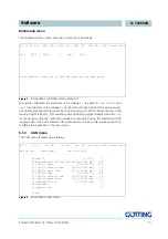
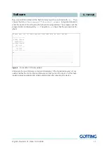
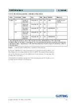
The meaning of the status bits is determined as follows:
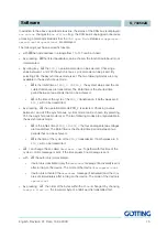
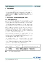
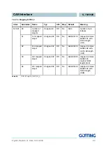
PDO_2 is sent with identifier 0x280 + node address. It contains exactly four 16bit word
(left-aligned) in the order Us1,Ud1,Us2, Ud2. The synchronous identifier which is up
to be received is 0x80. It can be read in index [1005,00].
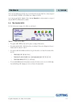
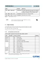
7.1.2
Receiving objects
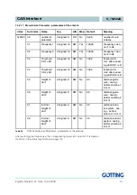
The frequency of the wires can also be changed using a non-cyclical receiving PDO.
Additionally, the RPDO can be deactivated/activated by setting/deleting the highest
bit in the corresponding PDO-COB identifier [1400,01].
The RPDO is expected on identifier 0x200 + node address. It contains 4 bytes for the
frequencies F1 and F2 in Hz. The order of the bytes within the 16bit words can be al-
tered using the CAN menu
L
(see 6.1.3 on page 14) or the SDO with index
0x2003,02 (Node config).
Bit no.
Value
Meaning
7
0x80
Us1 exceeded chosen threshold for channel 1
6
0x40
Us2 exceeded chosen threshold for channel 2
5
0x20
Toggle-Bit, changes its status after each transmission of PDO_1
4
0x10
calibration is active
3
0x08
DC monitoring Ud1 is OK
2
0x04
DC monitoring Ud2 is OK
1
0x02
not connected
0
0x01
Checksum of the EEprom - parameter is wrong.
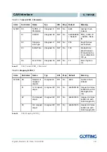
Table 6
CAN: meaning of the status bits
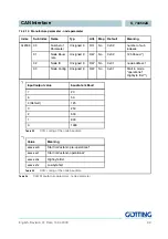
Channel
Number
Value range
derivation (theoretically)
Us1
Unsigned 16
0..65535
4*16*1024
Ud1
signed 16
-32768…..+32704
-4*16*512…..+4*16*511
Us2
Unsigned 16
0..65535
4*16*1024
Ud2
signed 16
-32768…..+32704
-4*16*512…..+4*16*511
Table 7
CAN: displayed numbers for PDO_2