CAN Interface
English, Revision 01, Date: 14.04.2009
18
7
CAN Interface
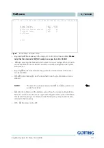
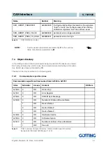
The node ID and the transfer rate have to be selected by using the serial monitor (de-
scribed in section 6.1 on page 11) or the corresponding SDOs.
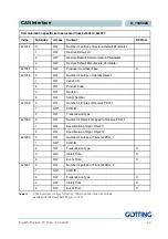
The measured values of the system are transmitted via two so called TxPDOs. They
can be parametrized using the SDOs. Additionally the frequencies of the two wires can
be altered using a non-cyclical RPDO. The CAN identifier can be deduced ny the node
adress (1 to 127).
7.1
Description of the process data objects (PDOs)
7.1.1
Transmission objects
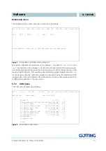
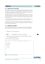
The node ID and the transfer rate have to be entered in the above described serial
monitor or the corresponding SDOs. The measured data of the system is transmitted
using two so called TxPDOs. The parametrization happens over SDOs or two RPDOs.
The measured data are allocated to particular places in the PDO, a dynamical map-
ping is not provided. The PDO mode can be set to cyclical, synchronous or a asyn-
chronous.
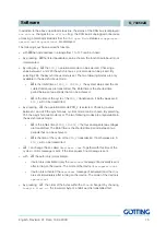
To assure that the BUS is working probably during the non-cyclical transmission
(asynchronous mode) the inhibit time in the CAN menu can be adjusted using the se-
rial monitor (see 6.1.3 on page 14). This is important as the the constant changes may
affect the BUS. A PDO can be transmitted cyclical anyway. The corresponding event
time is to choose and the inhibit time has to be set to 0.
A TxPDO can be activated permanently by choosing the asynchonous mode (255)
with inhibit time = 0, event time = 0 and saving of the parameters.
Additionally, it can be deactivated/activated by setting/deleting the highest bit in the
corresponding PDO-COB identifier [1800,01] or [1801,1] .
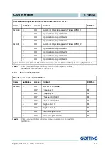
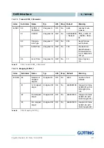
PDO_1 is sent with the identifier 0x180 + node address. It contains 5 bytes in which
the displayed status on the serial monitor as well as two distance values (left-aligned)
are contained. The order aof the transmission is status, X1, X2.
The order of the bytes within a 16bit word can be altered usin the CAN menu
L
(see
6.1.3 on page 14) or the SDO with the index 0x2002,03 (Nodeconfig).
Value
Number
Value range
Annotation
Status
unsigned 8
0..0xff
status bits according to Table 6 on page 19
X1
signed 16
-32640…..+32640
-128*255 [mm]…..+128*255 [mm]
X2
signed 16
-32640…..+32640
-128*255 [mm]…..+128*255 [mm]
Table 5
CAN: displayed numbers for PDO_1

