


Hardware
English, Revision 01, Date: 14.04.2009
10
The 16x oversampling and the use of a 10bit A/D converter lead to a value range of
the sum voltage of 16384, of the difference voltage of ±8192.
As in this range the DC offsets of the channels
have to
be compensated, a range of
about 16000 to ±8000 units is usable.
5.4
The Control LED
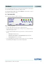
On the front panel a group of 5 LEDs can be found.
Figure 2
Postion of the LEDs
-
The green LED (PWR) presents the power voltage of the device
-
The yellow LEDs (CD1, CD2) show the exceeding of the sum voltage and the set
thresholds for channel 1 and 2.
-
The green LED (BUS) flashes after turning on the device. It shows the status of the
device:
-
Node stop:
LED flashes slowly
-
Node reset communication
and
node preoperational:
LED flashes fast
-
Node operational:
LED is lit continously
-
The red LED (ERR) starts to flash as soon as a CAN bus error occurs. Additionally
the red flashing LED displays an error in the set of parameters.