4.4 Connection to the Computer
Steps:
1. Insert one end of the network cable into the “NET” port of EzLogger Pro.
2. Insert the other end of the cable into the computer's Ethernet port.
Introduce
h
ow EzLogger Pro is connected to the computer.
When connecting to the computer, you need to use
commissioning
ProMate
software. Please refer to 5.1 for
software settings.
ProMate
14
4.4 Connection to the Computer
Steps:
Please make sure that the RS485 + of the environmental monitor
is connected to COM4 “A”
and
meter
of EzLogger Pro, and the RS485 - of the environmental monitor
is connected to COM4 “B”
and
meter
of EzLogger Pro. Environmental monitor ,
and other devices can only be connected to COM4.
meter
Description of COM4:
Port
Symbol
Description
COM4
A
RS485A, RS485 differential
B
RS485B, RS485 differential signal -
4.5 Connection to the Ripple Control Receiver
In Germany and parts of Europe, power grid companies use ripple control receivers to convert power grid
scheduling signals for dry contact transmission, and power stations need to use dry contact
communication method to receive power grid scheduling signals.
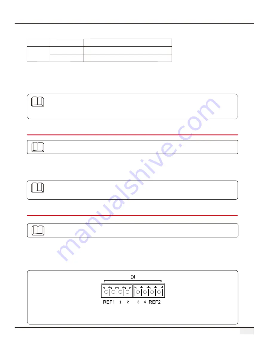
DI terminal interface of EzLogger Pro is as follows:
Introduce the functions of Ripple Control Receiver.
Figure 4.5-1 Schematic Diagram of EzLogger Pro DI Port
1. connect one end of the communication line to the RS485 port of the environment monitor and
the meter.
2. connect the other end of the communication line to the COM4 port of EzLogger Pro.


