Glow-worm ULTIMATE 30c Installation And Servicing Manual Download Page 5

0020167175_01 - 02/13 - Glow-worm

INTRODUCTION

1 Instructions 

guidance

1.1 Product 

documentation

The instructions are an integral part of the appliance and must be 

handed to the user on completion of the installation in order to 

comply with the current regulation.

• 

Carefully read the manual, to understand all the information 

to enable safe installation, use and servicing. No liability can 

be accepted in the event of damage for not complying with the 

guidance in this instruction manual.

These instructions consist of, Installation, Servicing, Fault Finding, 

Replacement of Parts and Spares. The instructions are an integral 

part of the appliance and must, to comply with the current issue of 

the Gas Safety (Installation and Use) Regulations, be handed to the 

user on completion of the installation.

1.2 

Explanation of symbols

a

 DANGER: 

Risk of injuries.

e

 DANGER: 

Risk of electric shock.

b

 ATTENTION: 

Risk of damage to the appliance or to its surroundings.

i

 IMPORTANT: 

Important information.

1.3 Guarantee 

registration

Thank you for installing a new Glow-worm appliance in your home.

Glow-worm appliances are manufactured to the very 

highest standard so we are pleased to o

 er our customers a 

Comprehensive 5 years Guarantee.

We recommend you complete and return as soon as possible 

your guarantee registration card. If your guarantee registration 

card is missing you can obtain a copy or record your registration 

by telephoning the Glow-worm Customer Service number 01773 

828100.

2 Appliance 

description

2.1 Safety 

devices 

2.1.1 Overheating 

safety

The appliance is designed to recognise the potential for an 

overheat lockout and will shutdown before this happens. 

2.1.2 Safety 

discharge 

valve

A safety discharge valve and discharge pipe are 

fi

 tted to the 

boiler. This valve must not be touched. 

 - The heating safety valve opens when the pressure in the 

heating circuit exceeds 3 bars.

• 

Should there be any discharge from the pipe, isolate the boiler 

electrical supply and call your installer or Glow-worm’s own 

service organisation.

2.1.3 Frost 

protection

The frost protection system operates the pump to start as soon 

as the temperature in the heating circuit falls below 12°C. The 

pump stops as soon as the temperature of the water contained 

in the heating circuit reaches 15°C.  If the temperature in the 

heating system falls below 7°C, the burner ignites until it reaches 

35°C. The frost-protection system is active when the appliance is 

switched on. The system alone cannot ensure that the installation 

is protected against frost. An separate frost thermostat is 

necessary to control the temperature of the system.

a

 DANGER: 

Your domestic water circuit (hot or cold) is not protected 

by the boiler.

2.1.4 

Condensate drain blockage

During freezing conditions this may be due to the forming of ice 

in the condense drain external to the house. In this case, a safety 

device shuts down the appliance.
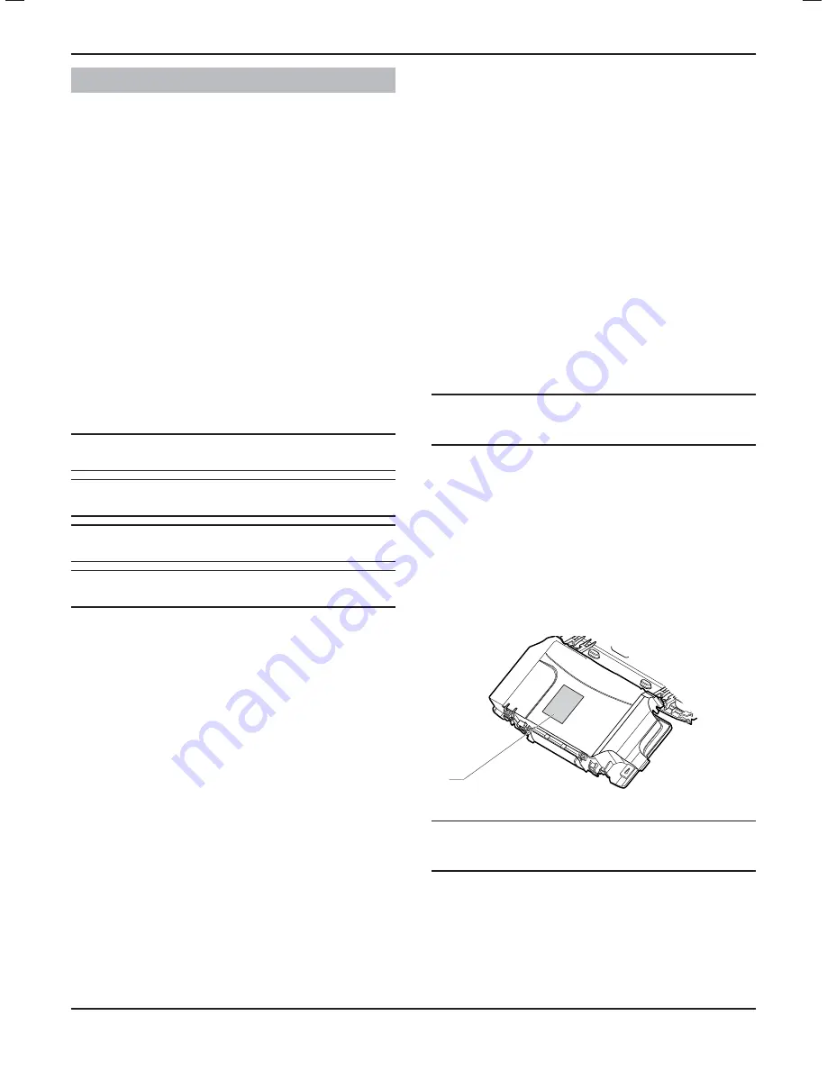
2.2 Data 

label

The data label certi

fi

 es the country where the appliance is 

intended to be installed.

Data label location:

1

Key

1 Data 

label

a

 DANGER: 

The appliance shall only be connected to the gas type(s) 

indicated on the data label.

• 

Refer to chapter "Technical Data" in the technical data section 

to see the de

fi

 nition of the abbreviations used on the data 

label.

INTRODUCTION

- 3 -

Summary of Contents for ULTIMATE 30c

Page 1: ...condens Installation and Servicing ULTIMATE 30c G C No 47 044 48 ULTIMATE 35c G C No 47 044 49...

Page 2: ......

Page 3: ...Appliance location 8 6 1 Location 8 6 2 Clearances 8 6 3 Ventilation 8 7 Appliance installation 9 7 1 Scope of delivery 9 7 2 Recommendations before installing 9 7 3 Dimensions 10 7 4 Mounting 11 8 Hy...

Page 4: ...shooting 28 14 1 Fault diagnosis 28 14 2 Fault memory 29 14 3 Fault codes 29 14 4 Functional flow diagram 31 15 Gas conversion adjustments 32 15 1 Settings 32 15 2 Restart re check commissioning 33 1...

Page 5: ...g safety The appliance is designed to recognise the potential for an overheat lockout and will shutdown before this happens 2 1 2 Safety discharge valve A safety discharge valve and discharge pipe are...

Page 6: ...ent person approved at the time by the Health and Safety Executive and that it meets the requirements of the appropriate Building Regulations The Benchmark Checklist can be used to demonstrate complia...

Page 7: ...onal test and check for safety 3 2 Regulations 3 2 1 Statutory requirements IMPORTANT Where no British Standards exists materials and equipment should be fit for their purpose and of suitable quality...

Page 8: ...of the boiler including any heating controls to the electrical supply MUST be through one common isolator and must be fused 3 Amp maximum 3 2 2 Other regulations Control of Substances Hazardous to Hea...

Page 9: ...trical power W 6 6 Operational mode electrical power Max W 151 151 Internal fuse rating on main PCB A 2 2 Index of electrical protection EN 60529 IPX4D IPX4D Description Unit 30 35 Gas connection O D...

Page 10: ...building it should be fitted in accordance with the Institute of Gas Engineers document IGE UP 7 1998 If in doubt seek advice from local gas undertaking or Glow worm 6 2 Clearances To allow periodic...

Page 11: ...estic flow is 1 0 bar The maximum working pressure of the domestic hot water circuit is 10 bar If the cold water supply pressure exceeds this then a pressure reducing valve must be fitted in the suppl...

Page 12: ...ng systems are shown diagrammatically see diagram below 3 2 1 4 7 6 5 Key 1 Heating flow circuit 2 Heating return circuit 3 Boiler 4 Double check valve assembly 5 Domestic cold water supply in 6 Tempo...

Page 13: ...ue 80 125 flue 130mm Use a 125mm diameter core drill for internal access only flue installation 60 100 flue 80 125 flue 150mm i IMPORTANT If flue extension pipes are to be used then a core drill size...

Page 14: ...s operation Do not use any solvent products due to the risk of damaging the circuit a DANGER Do not perform any hot work directly under the appliance this may cause damage to the appliance base Heat m...

Page 15: ...e pipe 2 Condensate outlet pushfit Make sure there is no protective plug fitted Connect the condensate pipe 1 to the condensate outlet 2 i IMPORTANT The pipe should have a fall of a least 2 5 44mm met...

Page 16: ...0020167175_01 02 13 Glow worm INCREASE PIPE SIZE 75 mm min 100 mm min Washing machine trap waste 44 2 5 INSTALLATION 14...

Page 17: ...Being a condensing boiler some pluming may occur from the flue outlet This should be taken into consideration when selecting the position for the terminal Carports or similar extensions of a roof onl...

Page 18: ...onal 90 bend is necessary or 2 at 45 the length L must be reduced by 1 m When using the Plume Management Kit the maximum lengths flue pipe A and B 60 100mm are A m 0 5 1 0 1 5 2 0 2 5 3 0 3 5 4 0 4 5...

Page 19: ...C 60 C 72 9 73 1 10 Electrical connections e DANGER Incorrect installation can cause electric shock or appliance damage The electrical connection of the appliance must be made only by a qualified engi...

Page 20: ...850C insulated cable not less than 0 75mm 24 0 20 A fused three pin plug and shuttered socket outlet may be used instead of a fused spur box provided that it is not used in a room containing a fixed...

Page 21: ...s as below Resistance to earth 1 Ohm Short circuit test L N Resistance to earth L E Polarity check 10 3 2 230V permanent supply 230V system controls a DANGER All cables connected to the appliance shou...

Page 22: ...4 13 5 14 6 15 7 16 8 17 9 18 X20 1 2 3 4 1 1 2 1 X21 Green Yellow Green Yellow 18 17 16 1 2 3 4 9 6 5 8 7 10 11 12 13 14 15 Key 1 Control accessories connector 2 Reserved for future use 3 Location fo...

Page 23: ...he gas supply Switch on the power supply to the appliance Make sure that the domestic hot water and heating functions on your appliance are not activated 11 3 Filling the CH system Central heating Mak...

Page 24: ...been installed in accordance with the instructions Check the integrity of the flue system and flue seals Check the integrity of the appliance combustion circuit and relevant seals Check that all inte...

Page 25: ...top watch at least 10 minutes after the burner has lit see table below for approximate rates Gas rates G20 Gas rates G31 approx after 10 mins from cold Model MIN MAX MIN MAX m3 h ft3 h m3 h ft3 h kg h...

Page 26: ...the user IE it is necessary to complete a Declaration of Conformity to indicate compliance to I S 813 An example of this is given in the current edition of I S 813 12 Specified Adjustment 12 1 Heating...

Page 27: ...ure measured by the external sensor no d 67 Time remaining before the end of the anti cycle in heating mode min Display the time remaining before the end of the anti cycle no d 71 Maximum temperature...

Page 28: ...ivated 1 activated 0 yes 12 4 Status of the appliance Press button for more than 3 seconds to learn the current state of functioning of the appliance The screen displays S and the state of the applian...

Page 29: ...installed check the operation of the appliance Start the appliance to ensure that any adjustments operate correctly and check that the appliance operates safely Check the gas tightness and water tigh...

Page 30: ...Make sure that the electricity supply has not been interrupted and that the appliance is connected correctly See chapter Trouble shooting Fault diagnosis Check the electrical installation Check the ap...

Page 31: ...ssure of the installation 0 3 bar Return water valve closed Pump disconnected Leak in the installation Fill the installation Purge the installation Check the pump connections Check the flow and return...

Page 32: ...nce Check temperature sensors connections Replace faulty sensors F73 Heating circuit pressure sensor fault The sensor is shorted or disconnected Check the sensor s connections Check the sensor F74 Hea...

Page 33: ...0020167175_01 02 13 Glow worm 14 4 Functional flow diagram 14 4 1 Central Heating 14 4 2 Domestic Hot Water MAINTENANCE 31...

Page 34: ...converted See chapter Commissioning Tools required to make the conversion are a 4mm Allen key and an electricians screwdriver Having checked the appliance and system have been installed in accordance...

Page 35: ...eating circuit of the boiler only by closing the heating flow and return isolating valves See chapter Hydraulic connection Gas and water connections Open the drain point 2 Attach a length of hose 1 if...

Page 36: ...eck that the pressure sensor is working properly The pressure must be displayed on the screen Check the pressure of the expansion vessel 17 1 2 Other checks Check the CO2 rate in the fuel and compare...

Page 37: ...2 Preliminaries Prior to during servicing and after any maintenance or changed parts the following inspection must be carried out The integrity of the flue system and flue seals The integrity of the...

Page 38: ...to achieve the required results for either the combustion or gas rates it will be necessary to complete a full service of the appliance and then repeat the combustion check procedure If after servicin...

Page 39: ...Use protective gloves 5 3 2 4 1 6 Key 1 Condensate cleaning cap 2 Condensate pipe 3 Condensate outletv 4 Condensate retaining screw 5 Condensate trap 6 Hose Place a container under the condensate tra...

Page 40: ...t exchanger 12 Burner door seal 13 Burner 14 Gas valve 15 Fan 16 Fan connection 17 Gas pipe 17 8 1 Spark electrode Disconnect the electrode inlet 3 and the grounding cable 2 Remove the 2 spark electro...

Page 41: ...tion check On completion of the service the Benchmark Service Record sould be completed 18 Replacement of Parts Do not use reconditioned or copy parts only use original parts supplied by Glow worm If...

Page 42: ...5 Remove the steel washer 4 Remove fibre washer 1 Remove the glass 3 18 3 1 Expansion vessel B C D E A 3 2 1 4 2 1 Key 1 Connector 2 Expansion vessel 3 Upper support bracket 4 Retaining screw 5 Gaske...

Page 43: ...17 Automatic air vent 18 Expansion vessel pipe clip 19 Automatic air vent retaining clip 20 Pump head retaining screws 21 Pump housing 22 Pump head connector 23 Plate to plate heat exchanger retaining...

Page 44: ...urise the boiler 18 4 5 Flow sensor and impeller Remove the the electrical connection 12 Unclip the flow sensor 13 Unscrew the impeller housing 28 and remove the impeller 18 4 6 Bypass Drain the boile...

Page 45: ...ut 13 Combustion burner door assembly seal 14 Burner gasket 15 Burner 16 Burner retaining screw 17 Heat exchanger retaining screw 18 Heat exchanger retaining bracket 19 Burner gate retaining screw 20...

Page 46: ...t exchanger out Drain the boiler heating and hot water circuits as described in the appropriate chapter Draining Remove the flue connection Undo the two screws located on the top of each side panel Re...

Page 47: ...18 6 Condensate trap b ATTENTION Condensate is mildly acidic Wear protective gloves 5 3 2 4 1 6 Key 1 Condensate reservoir 2 Condensate discharge 3 Condensate outlet 4 Condensate retaining screw 5 Con...

Page 48: ...to the PCB When refitting the user interface ensure the leads are not trapped 18 7 4 Mains supply cable e DANGER The main supply cable must be replaced by a qualified and competent electrician If the...

Page 49: ...low and return 4 0020097279 Gas valve 5 0020038441 Electrode assembly 6 0020118159 User interface PCB Key No Part No Description GC Part No 7 0020136541 Plate to plate heat exchanger 30c 0020173017 Pl...

Page 50: ...olystyrene end packs Remove top polystyrene pack with fittings Positioning of Appliance for Final Installation no obstructions Recommend 2 persons lift appliance to position into place Fit bracket sec...

Page 51: ...Declaration of Conformity Installation Commissioning and Service Record...

Page 52: ...a...

Page 53: ...r ID Number Comments Signature SERVICE 7 Date EnerJ I ciency Checklist completed Yes No Engineer Name Company Name Telephone Number Engineer ID Number Comments Signature SERVICE 9 Date EnerJ I ciency...

Page 54: ......

Page 55: ......

Page 56: ...ing changes GLOW WORM Nottingham Road Belper Derbyshire DE56 1JT Because of our constant endeavour for improvement details may vary slightly from those shown in these instructions www glow worm co uk...

Reviews: