


Supplied By www.heating spares.co Tel. 0161 620 6677
24
221473B
11 Commissioning
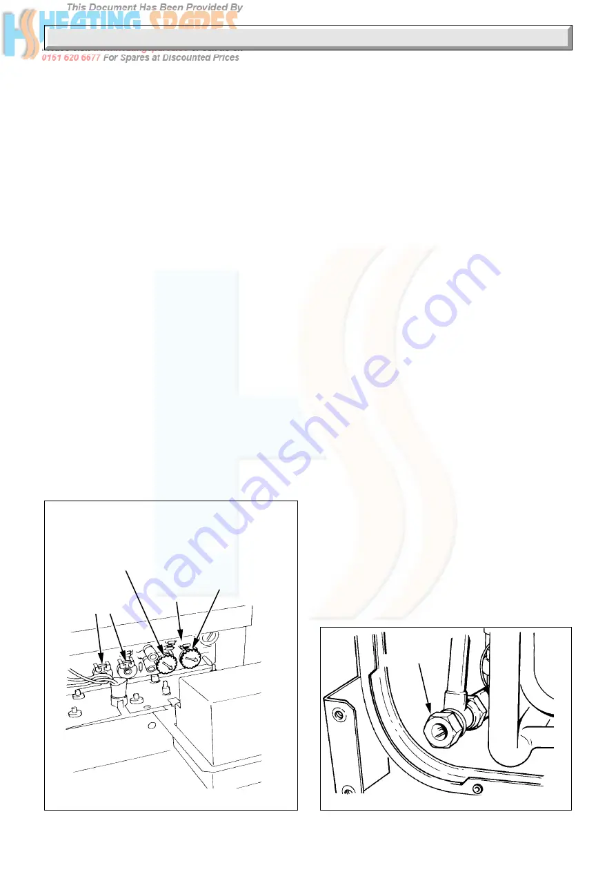
DOMESTIC
HOT WATER
THROTTLE
Diagram 11.4
2801
5085
Diagram 11.3
HOT WATER
GAS
PRESSURE
ADJUSTER
CONTROL
BOARD
DO NOT
ADJUST
CENTRAL
HEATING
GAS PRESSURE
ADJUSTER
11.7 Burner Pressure - Heating
The burner pressure is factory preset and no adjustment should
be required.
Check that all remote heating system controls, room thermostats,
time switches and the like are switched on/programmed and
calling for heat.
Set switch “C” to “ON”, white flash showing, see diagram 11.1.
The pump will circulate water through the boiler and the main
burner will light.
Check that the burner pressure, with the heating system cold
and temperature control knob at maximum, to prevent any
modulation of the gas pressure, is within +/- 0.2mbar (+/-0.08in
wg), of 6.2mbar (2.6in wg). If the burner pressure is incorrect,
it may be adjusted to the correct setting by turning the central
heating gas pressure adjuster (potentiometer) using an insulated
screwdriver, see diagram 11.3. Turn the adjuster slowly,
always making adjustment by reducing below the required
pressure then increasing up to the required setting, turn clockwise
to increase.
Isolate the boiler from the electrical supply.
Remove the pressure gauge and tighten the test point screw.
Test for gas soundness around the burner pressure test point
with the main burner alight, using a suitable leak detection fluid.
Refit the cover of the control housing and refit the housing to the
boiler.
11.8 Temperature Settings
The domestic hot water outlet and central heating flow
temperatures are factory preset and sealed.
The nominal temperature setting for the Domestic Hot Water
outlet is 55
o
C (131
o
F) at a flow rate of 3.6Litre a minute (0.8gal/
min).
The nominal flow temperature setting for central heating is 82
o
C
(180
o
F), with the user central heating temperature control set to
maximum.
11.9 Heating System Commissioning
Check that all remote system controls and integral clock are
calling for heat.
Fully open radiator valves, flow control valve “A” and bypass
valve “B”, see diagram 4.2.
Set the heating system in operation and balance the radiators.
Adjust the flow control valve “A” to achieve the required system
differential temperature between the boiler flow and return.
Turn off all radiators, then adjust bypass valve “B” to achieve the
same temperature difference between the boiler flow and
return.
Refer to Section 4.6 and diagram 4.1.
Allow the system to reach maximum temperature then switch
off, isolate the boiler from the electrical supply and drain the
system rapidly whilst hot, using the external drain tap at the
lowest point of the system.
Fill and vent the system as described previously in Section 11.2.
Add the inhibitor, if required, refer to Section 4.10.
Lower the pressure to the initial cold fill design pressure, using
the draining tap, close to the boiler, refer to Table 2 and 4
Section 4.11.
Set pointer on the pressure gauge to this pressure.
Lock or remove the handles from the spindles of flow control
valve “A” and bypass valve “B” to prevent unauthorised
adjustment.