20
A - 4. Encoder Output Connector
Table A - 4.1. Encoder Output Designations: Labeled as P2 on servo drive.
Table A - 4.2. Encoder Output Connector
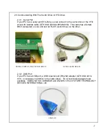
A - 5. Serial Communication Connector
Table A - 5.1. Serial Communication Designations: Labeled as P3 on servo
drive.
Table A - 5.2. Encoder Output Connector
A - 6. Power and Signal Wiring
6.1. Recommend 3-phase input, 3-phase output, and chassis GND power wiring, 8 AWG (8.36 mm
2
)
or larger, 105°C rated PVC or better.
6.2. Recommend BUS+, BUS Return, and brake power wiring, 10 AWG (5.26 mm
2
) or larger, 105°C
rated PVC or better.
6.3. Recommend all signal wiring, 22 AWG (0.326 mm
2
) or larger, 105°C rated PVC or better.
Connector Description/Type
5-Pin Terminal Block
Terminal Block,
5 Position, 22-12 AWG
Phoenix Contact 1934890
Designations
Pin#
I/O
Name
Function
8
Power
GND
Encoder Power Return
9
Output
EOA +
Encoder Channel A +
10
Output
EOA -
Encoder Channel A - (not)
11
Output
EOB +
Encoder Channel B +
12
Output
EOB -
Encoder Channel B - (not)
Connector Description/Type
8-Pin Male Mating Connector
Standard Commercial, RJ-45
Commercial, RJ45
Pin#
I/O
Name
Function
1
Input
RS-485 RX +
RS-485 R
2
Input
RS-485 RX -
RS-485 Receive -
3
Reserved
Reserved
Reserved
4
Input/output
COMMON
Logic Ground
5
Output
RS-232 TX
RS-232 Transmit
6
Input
RS-232 RX
RS-232 Recieve
7
Output
RS-485 TX +
RS-485 Tr
8
Output
RS-485 TX -
RS-485 Transmit -
Summary of Contents for SMB9675-1A-1
Page 2: ......
Page 11: ...Before and after photos of a typical installation 9...
Page 30: ...28...
Page 31: ...29...
Page 35: ......


