


2
di 100Nm; in seguito serrare i grani M8 “H”
applicando un momento torcente di 10Nm.
Per collegare la staffa “N” (vedere
figura
1
-
2
-
3
-
4
) alla struttura metallica o alla traversa, in
caso di foro passante, utilizzare la soluzione
con bullone M18 e relative rondelle piane
e dentate in acciaio zincato. La larghezza
minima della struttura metallica o della traversa
alla quale fissare la staffa “N” deve essere di
almeno 10cm.
Per installare l’apparecchio su superficie
orizzontale e foro cieco (struttura acciaio),
utilizzare almeno 1 vite M18 in posizione
centrale, per rotazione azimutale
dell’apparecchio, e relativa rondella piana e
dentata in acciaio zincato, utilizzando i fori
presenti sulla staffa “N” (vedere
figura 2a
).
Non montare su strutture soggette a forti
vibrazioni.
Non montare a parete.
Per collegare l’apparecchio sotto la struttura
metallica o la traversa, svitare la staffa “N”
allentando i grani M8 “H” e le due viti M12 inox
testa esagono “E”, ruotare di 180° la staffa
N/m, infine serrare a fondo le due viti M12 inox
testa esagono “E” applicando un momento
torcente di 100N ed i grani M8 “H” applicando
un momento torcente di 10Nm (vedere
figura
2b
).
Se non diversamente specificato , è opportuno
mantenere una distanza di almeno 1,3 metri fra
l’interasse dei fori di fissaggio proiettori della
struttura metallica”
Per la connessione forcella - struttura metallica
utilizzare esclusivamente bulloneria M18
in acciaio zincato applicando un momento
torcente di 100Nm.
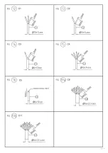
Eseguire il puntamento dell’apparecchio
utilizzando la scala goniometrica “F” (vedere
figura
9
) ed il relativo riferimento presente
sulla staffa: posizione di riferimento forcella su
“0” per avere apparecchio tilt 0°, su “15” per
avere tilt 15° ad esempio.
In presenza di visiera utilizzare scala
goniometrica “LOUVRE”, quindi per avere tilt
0° posizione di riferimento su forcella “OL”,
per avere tilt 15° su “15L” ad esempio.
Una volta puntato l’apparecchio, serrare le due
viti M12 inox testa esagono “E” applicando un
momento torcente di 100Nm.
Posizioni di funzionamento: vedere
figura
10
.
Evitare in modo assoluto di far funzionare gli
apparecchi installati all’esterno durante le ore
diurne, per evitare funzionamenti anomali della
componentistica elettronica dovuti alle alte
temperature ambientali.
Non installare l’apparecchio vicino a fonti
di calore o in posizioni geometriche tali da
superare il limite termico dell’apparecchio.
La sostituzione delle sorgenti luminose (matrici
LED) può essere effettuata solo da personale
FAEL in sede FAEL Spa.
Qualsiasi tipo di manutenzione alla
componentistica può essere effettuata solo da
personale qualificato.
Sostituire gli schermi di protezione in vetro
danneggiati, utilizzando esclusivamente
ricambi Fael e verificare, prima della chiusura
dell’apparecchio, che tutti i componenti siano
nella loro posizione originale.
Tmax vetro = 200° C
Per garantire la sicurezza dell’apparecchio,
l’installazione deve essere eseguita da
personale qualificato che si deve attenere
scrupolosamente alle istruzioni ivi riportate.
Non fissare la sorgente luminosa durante il
funzionamento.
Una volta terminata l’installazione, conservare
il foglio di istruzioni.
Per tutte le versioni:
nella realizzazione di impianti a LED con
LEDMASTER ONE è indispensabile introdurre
altri surge protectors nel quadro generale
(SPD tipo 1), nei quadri di zona (SPD tipo
1-2) e coordinarli con il surge protector del
proiettore
1
-
9
) by applying 100Nm torque; then tighten
the M8 grains “H” by applying 10Nm torque.
To connect the bracket “N” (check the
figure
1
-
2
-
3
-
4
) to the metal frame or to the crossbar
in case of through-hole, use an M18 bolt and
flat or toothed zinc-plated washers.
The minimum width of the metal structure or
of the crossbar to which the bracket “N” is
secured must be at least 10cm.
To install the projector on horizontal surfaces
and in case of blind holes (steel structure), use
at least 1 M18 screw in the centre position
to ensure azimuthal rotation, and the related
flat and toothed zinc-plated washer; use the
holes provided on the bracket “N” (check the
figure
2a
).
Do not mount the projector in areas exposed to
strong vibrations.
Not intended for wall mounting.
To connect the luminaire under the metal
frame or beam, loosen the “N” bracket using
the M8 grub screws, “H”, and the two M12
stainless steel hex-head screws, “E”, rotate
the “N” bracket to 180° and then tighten the
two M12 stainless steel hex-head screws, “E”,
to a tightening torque of 100N and the M8 grub
screws, “H”, to a tightening torque of 10Nm
(see
figure
2b
).
Unless otherwise specified, a distance of
at least 1.3 metres should be maintained
between the centre distance of the floodlight
fixing holes on the metal frame
To connect the fork to the metal structure use
exclusively M18 hardware made from zinc-
plated steel by applying a torque of 100Nm.
Aim the projector using the goniometric
scale “F” (check the
figure
9
) and the
related reference provided on the bracket:
for example, “0” fork reference position for a
0° luminaire tilt, “15” reference position for a
15° tilt.
If the luminaire is fitted with a glare shield, use
the “LOUVRE” goniometric scale; therefore,
for a 0° tilt angle the fork reference position
should be “OL”, and for a 15° tilt angle, the
reference position should be “15L”.
Once the appliance is aimed, tighten the two
M12 hex head screws “E” by applying a torque
of 100Nm.
Operating position: check the
figure
10
.
Avoid using the luminaires installed outdoors
during daylight to prevent any malfunctions
of the electronic components due to the high
temperatures.
Do not install the appliance near heat sources
or in geometric positions that exceed the
thermal capacity of the unit.
The light sources (LED matrices) can be
replaced exclusively by FAEL personnel at Fael
Spa premises.
Any type of maintenance operation on the
components can only be performed by
qualified personnel.
Change damaged glass protection screens,
using Fael spare parts exclusively and,
before closing the appliance, check that the
components are in their original positions.
Tmax glass = 200° C
To ensure the proper and safe operation of the
projector, the installation operations must be
carried out by qualified personnel, according
to the instructions herein.
Do not stare at the light source during
operation.
Keep the instruction sheet after finishing the
installation.
For all versions:
when installing the LEDMASTER ONE LED
systems it is essential to equip the main
panel (SPD type 1) or the local panels (SPD
type 1-2) with additional surge protectors
and coordinate them with the surge
protector of the floodlight
M8 “H” en appliquant un moment de torsion
de 10Nm.
Pour fixer l’étrier “N” (voir
figure
1
-
2
-
3
-
4
)
à la structure métallique ou à la traverse, en
cas de trou passant, utiliser la solution avec
boulon M18 et rondelles plates et dentées en
acier zingué adaptées.
La largeur minimum de la structure métallique
ou de la traverse sur laquelle fixer l’étrier “N”
doit être de 10 cm au minimum.
Pour installer l’appareil sur des surfaces
horizontales et trou borgne (structure acier),
utiliser au minimum 1 vis M18 en position
centrale, pour rotation azimutale de l’appareil,
et rondelle plate et dentée en acier zingué
adaptée, à l’aide des trous présents sur l’étrier
“N” (voir
figure
2a
).
Ne pas monter sur des structures subissant de
fortes vibrations.
Ne pas monter au mur.
Pour brancher l’appareil sous la structure
métallique ou la traverse, dévisser l’étrier
“N” en desserrant les grains M8 “H” et les
deux vis M12 inox tête hexagonale “E” et faire
pivoter l’étrier “N/m” de 180° puis serrer à
fond les deux vis M12 inox tête hexagonale
“E” en appliquant un moment de torsion de
100N et les grains M8 “H” en appliquant un
moment de torsion de 10Nm (voir
figure
2b
).
Si non spécifié autrement, il convient de
maintenir une distance d’un minimum de
1,3 mètre entre l’entre-axes des orifices
de fixation des projecteurs de la structure
métallique”.
Pour fixer la fourche - structure métallique,
utiliser exclusivement de la boulonnerie M18
en acier zingué en appliquant un moment de
torsion 100Nm.
Pointer l’appareil à l’aide de l’échelle
goniométrique “F” (voir
figure
9
) et sa
référence correspondante, présente sur
l’étrier: position de référence fourche sur “0”
pour avoir appareil tilt 0°, sur “15” pour avoir
tilt 15°, par exemple.
En présence de visière, utiliser une échelle
goniométrique “LOUVRE” et pour avoir tilt 0°,
position de référence sur fourche “OL”, pour
avoir tilt 15° sur “15L”, par exemple.
Une fois l’appareil pointé, serrer les deux vis
M12 inox à tête hexagonale “E” en appliquant
un moment de torsion de 100Nm.
Positions de fonctionnement: voir
figure
10
.
Éviter absolument de faire fonctionner
les appareils installés à l’extérieur durant
les heures du jour, afin d’éviter des
fonctionnements anormaux des composants
électroniques dus à des températures
ambiantes élevées.
Ne pas installer l’appareil près de sources de
chaleur ou dans des positions géométriques
surchauffant l’appareil.
Le remplacement des sources lumineuses
(matrices LED) ne peut être effectué que par
le personnel FAEL Spa, dans ses usines.
La maintenance des composants ne peut être
effectuée que par du personnel qualifié.
Remplacer les écrans de protection en verre
endommagés en utilisant exclusivement des
pièces de rechange Fael et, avant de fermer
l’appareil, vérifier que tous les composants se
trouvent bien dans leur position d’origine.
Tmax verre = 200° C
Pour garantir le bon fonctionnement de
l’appareil, l’installation doit être effectuée
par des personnes qualifiées qui devront
respecter scrupuleusement les instructions
reportées.
Ne pas fixer la source lumineuse durant le
fonctionnement.
Au terme de l’installation, conserver le feuillet
d’instructions.
Pour toutes les versions:
pour la réalisation d’installations à LED
avec LEDMASTER ONE, il est indispensable
d’introduire d’autres surge protectors
dans le cadran général (SPD type 1), dans
les cadrans de zone (SPD type 1-2) et de
les coordonner avec le surge protector du
projecteur.
Abbildungen 1
-
9
) mit einem Drehmoment von
100Nm festziehen. Dann die Schrauben M8 “H“
mit einem Drehmoment von 10 Nm festziehen.
Zur Verbindung der Halterung “N” (siehe
Abbildung
1
-
2
-
3
-
4
) an der Metallstruktur oder
am Querträger, im Falle eines Durchgangsloch, die
Lösung mit Schraube M18 und die dazugehörigen
flachen und verzahnten Unterlegscheiben aus
verzinktem Stahl verwenden.
Die Mindestbreite der Metallstruktur oder des
Querträgers, an dem die Halterung “N“ befestigt
werden muss, muss mindestens 10 cm betragen.
Zur Installation des Gerätes auf einer horizontalen
Fläche und Sackloch (Stahlstruktur), mindestens 1
Schraube M18 in mittlerer Position für die azimutale
Drehung des Gerätes und die dazugehörige flache
und gezahnte Unterlegscheibe aus verzinktem
Stahl verwenden, dazu das Loch an der Halterung
“N“ nutzen (siehe
Abbildung
2a
).
Nicht an Strukturen mit starken Schwingungen
montieren.
Nicht an der Wand montieren.
Um das Gerät unter der Metallstruktur oder dem
Querträger zu befestigen, die Halterung “N“
abschrauben durch Lösen der M8-Schrauben
“H“ und der beiden M12-Sechskantschrauben
aus Edelstahl “E”. Die Halterung N/m um
180° drehen, abschließend die beiden M12-
Sechskantschrauben “E“ aus Edelstahl mit einem
Drehmoment von 100N und die M8-Schraube “H“
mit einem Drehmoment von 10Nm fest anziehen
(siehe
Abbildung
2b
).
Sofern nicht anders angegeben, wird empfohlen
einen Abstand von mindestens 1,3 Meter zu dem
Mittenabstand der Scheinwerferbefestigungslöcher
der Metallstruktur einzuhalten”
Für die Verbindung Gabel-Metallstruktur nur
M18-Schrauben aus verzinktem Stahl mit einem
Drehmoment von 100 Nm verwenden.
Richten Sie das Gerät aus, verwenden Sie dazu
die Goniometerklasse “F” (siehe
Abbildung
9
)
und die entsprechende Referenz an der Halterung:
Referenzposition der Gabel auf „0”, um die
Neigung des Geräts auf 0° zu bringen, auf “15”
um die Neigung auf 15° zu bringen, zum Beispiel.
Bei Vorhandensein einer Goniometerklasse
“LOUVRE”, muss daher um die Neigung auf 0°
zu bringen, die Referenzposition an der Gabel
“OL” sein, um die Neigung auf 15° zu bringen, auf
“15L” sein.
Wenn das Gerät ausgerichtet ist, die beiden
Edelstahl-Sechskantschrauben M12 “E” mit einem
Drehmoment von 100Nm anziehen.
Arbeitspositionen: siehe
Abbildung
10
.
Den Betrieb der im Freien installierten
Geräte während der Tageslichtstunden
unbedingt vermeiden, um Störungen der
elektronischen Komponenten aufgrund hoher
Umgebungstemperaturen zu vermeiden.
Installieren Sie das Gerät nicht in der Nähe von
Wärmequellen oder in geometrischen Positionen,
um die thermische Grenze des Geräts zu
überwinden.
Der Austausch der Lichtquellen (LED-Matrix) darf
nur von qualifiziertem Personal von FAEL bei FAEL
Spa durchgeführt werden.
Die Wartungsarbeiten an den Komponenten dürfen
nur von qualifiziertem Personal durchgeführt
werden.
Ersetzen Sie beschädigte Glasabschirmungen
nur mit Ersatzteilen von Fael und überprüfen Sie,
ob sich alle Komponenten in ihrer ursprünglichen
Position befinden, bevor Sie das Gerät schließen.
Tmax Glas = 200° C
Um die Sicherheit des Geräts zu gewährleisten,
muss die Installation von qualifiziertem Personal
durchgeführt werden, das die hier angegebenen
Anweisungen befolgen muss.
Bringen Sie die Lichtquelle während des Betriebs
nicht an.
Wenn die Installation abgeschlossen ist, bewahren
Sie die Anweisungen auf.
Für alle Versionen:
Bei der Installation von LED-Systemen mit
LEDMASTER ONE ist es unbedingt erforderlich,
weitere Überspannungsschutzgeräte im
allgemeinen Schaltschrank (SPD Typ 1), in den
Schalttafeln der Zone (Typ 1-2) einzusetzen
und mit dem Überspannungsschutz des
Scheinwerfers abzustimmen.
5
Summary of Contents for 514084500
Page 1: ...Glamox O92 O93 ASY User manual ...
Page 6: ...3 3 6 ...
Page 7: ...4 7 ...
Page 8: ...5 5 8 ...
Page 14: ...11 14 ...
Page 16: ...13 13 16 ...
Page 17: ...14 17 ...
Page 18: ...15 18 ...
Page 20: ...17 20 ...
Page 22: ...19 22 ...
Page 24: ...21 24 ...
Page 26: ...23 26 ...
Page 28: ...25 28 ...
Page 31: ...28 31 ...
Page 32: ...29 32 ...
Page 33: ...30 33 ...
Page 35: ...32 35 ...
Page 36: ...33 36 ...
Page 38: ...35 Note 38 ...
Page 39: ...39 ...


