background image

9

INSTALLATION INSTRUCTIONS

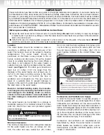
Temperature and Pressure-Relief Valve

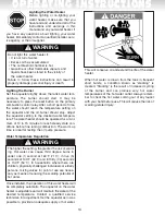
DO NOT

plug the temperature and pressure-

relief valve or its discharge line.

DO NOT

remove

the relief valve. Make sure the relief valve is prop-
erly sized for the water heater. If the relief valve
continuously discharges water, call a qualified
service technician to correct the problem. Failure
to follow these instructions can result in property
damage, personal injury or death.

To protect from excessive pressure and/or temperature,
the manufacturer has installed a temperature and
pressure-relief valve that meetswith the requirements
of the Standard for Relief Valves and Automatic Gas
Shut-Off Devices for Hot Water Supply Systems, CSA
4.4, in Canada, and ANSI Z21.22, in the United
States. This relief valve has a maximum set pressure
that does not exceed the hydrostatic working pressure
of the water heater (150 psi = 1,035 kPa) and a BTU/h
rating equal to or greater than the input rating, as
shown on the water heater rating plate. It should never
be plugged or removed from the opening marked for it
on the water heater.

If this relief valve should needs to be replaced, use
only a new temperature and pressure-relief valve.
Never install an old or existing relief valve, as it 
may be damaged or inadequate for the working
requirements of the new water heater. This new relief
valve must meet with all local codes or, at a 
minimum, the requirements listed above. Never
install any other type of valves between the relief
valve and the water heater.

A discharge line must be installed into the relief
valve.

The discharge line:

• Must not be smaller than the outlet pipe size of

the relief valve.

• Must not terminate less than six (6) inches (15.2

cm) and not more than twelve (12) inches (30.5
cm) above a floor drain.

• Must not be restricted in any way. Do not thread,

cap or in any way restrict the end of this outlet.

• Must be of a material capable of withstanding

210˚F (99˚C) without distortion.

• Must be installed to allow complete drainage of

the relief valve and discharge line.

• Must terminate at an adequate free-flowing drain.

Pressure Build-up in a Water System 

When the water heater operates, the heated water
expands creating a pressure build-up. This is a 

natural function and is one of the reasons for
installing a temperature and pressure-relief valve. If
the cold water supply line has a built-in water meter,
check valve or pressure-reducing valve, a suitable
expansion tank must be installed to prevent pressure
build-up or water hammer effect. Otherwise, the 
warranty will be void 

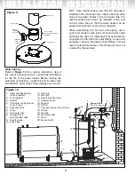
(see Figure 10)

. An indication

of pressure build-up is frequent discharges of water
from the relief valve. If the relief valve discharges
water on a continual basis, it may indicate a 
malfunction of the relief valve and a qualified service
technician must be called to have the system
checked and the problem corrected.

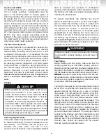
Filling the Water Heater

NEVER

operate the water heater unless it is

completely filled with water. Failure to follow this
instruction can result in premature failure of the
water heater that is not covered by the warranty.

Check that all of the water piping connections have
been made. To fill the water heater:

1) Make sure that the water heater drain valve is

closed by inserting a flat head screwdriver into the
slot on the head of the drain valve and turning the
knob clockwise         .

2) Open the cold water supply manual shut-off valve.

This valve must remain open, as long as the water
heater is in use. Never operate the water heater
with the cold water supply manual shut-off valve
closed.

3) To make sure the water heater is completely filled

with water, open hot water faucets to let the air out
of the water heater and plumbing system. Leave
the faucets open until a constant flow of water is
obtained.

4) Check all of the plumbing connections to make

sure there are no leaks.

Oil Supply

The entire fuel system should be installed in accor-
dance with all local codes or, in the absence of such
codes, the latest edition of the CAN/CSA B139,
Installation for Oil Burning Equipment, in Canada,
and/or the latest edition of the Installation of Oil
Burning Equipment, NFPA 31, in the United States.
Use only approved fuel oil tanks, piping, fittings, oil
filters and any other fuel handling components.
Install the oil filter as close to the burner as possible.
For further details of the oil supply tank and piping
requirements, please refer to the instructions and

WARNING

WARNING

Summary of Contents for RESIDENTIAL OIL-FIRED WATER HEATER

Page 1: ... not entirely followed a fire or explosion may result causing property damage per sonal injury or death DO NOT STORE use gasoline or any other flammable vapours or liquids in the vicinity of this or any other appliance DO NOT USE gasoline crank case oil or oil containing gasoline DO NOT TAMPER with the unit or controls DO NOT LEAVE paper or rags close to the burner or the water heater WHAT TO DO I...

Page 2: ...ntilation Air Supply 3 Requirements for Unconfined Spaces 4 Requirements for Confined Spaces Indoor Combustion and Ventilation Air 4 Requirements for Confined Spaces Outdoor Combustion and Indoor Ventilation Air 4 Requirements for Confined Spaces Outdoor Combustion and Ventilation Air 4 Air duct sizing 5 Louvers and Grilles 6 Corrosive Atmospheres 6 Venting 6 Chimney requirements 6 Flue piping 6 D...

Page 3: ...heater to operate properly it must be supplied with an uninterrupted flow of clean combustion and ventilation air The area around the water heater must always be kept clean and clear of debris An inadequate supply of air to the water heater will produce a bright yellow burner flame causing soot ing in the combustion chamber on the burner and in the flue tube This can result in damage to the water ...

Page 4: ...ly communi cating with interior areas that have in turn adequate infiltration from the outdoors Requirements for Confined Spaces Outdoor Combustion and Indoor Ventilation Air A water heater that is located in a confined space and that obtains its combustion air from outdoors and ventilation air from within the conditioned space of the building should be provided with two permanent openings one nea...

Page 5: ...losure b horizontal duct s as shown in Figure 7 with an equivalent length of less than 50 ft 15 m having a free flow area of not less than one 1 square inch per 2 000 BTU h 11 cm2 kWh of the total input of all oil fired appliances in the enclosure and c air openings that communicate directly with the outdoors as shown in Figure 6 having a free flow area of not less than one 1 square inch per 4 000...

Page 6: ...nnected to a ver tical chimney The chimney must be properly con structed and sized clean and free of soot creosote and obstructions able to generate sufficient draft to evacuate the products of combustion outdoors and be lined with a tile or metal liner Inspect the chimney and make any repairs necessary before installing the water heater To prevent downdrafts the chimney flue should extend at leas...

Page 7: ...tional Electrical Code NFPA 70 in the United States Before installing the switch remember to DIS CONNECT THE POWER SUPPLY to the water heater Failure to follow these instructions can result in property damage personal injury or death Installation 1 Install the pre assembled flue collar blocked vent switch assembly over the flue outlet on the water heater see Figure 9 2 Wire the switch to the aquas...

Page 8: ...is imperative that open flame is not applied to the inlet and outlet fittings as heat will damage or destroy the plastic lined fittings This will result in premature failure of the fittings which is not covered by the warranty 8 INSTALLATION INSTRUCTIONS FLUE COLLAR BLOCKED VENT SWITCH VENT PIPE FLUE OUTLET MANUAL RESET BUTTON FLUE COLLAR BLOCKED VENT SWITCH ASSEMBLY Figure 9 Figure 10 1 Flue coll...

Page 9: ...ystem When the water heater operates the heated water expands creating a pressure build up This is a natural function and is one of the reasons for installing a temperature and pressure relief valve If the cold water supply line has a built in water meter check valve or pressure reducing valve a suitable expansion tank must be installed to prevent pressure build up or water hammer effect Otherwise...

Page 10: ... proper burner settings Wiring This water heater uses an external electrical source for power It must be electrically grounded in accordance with all local codes or in the absence of such codes the latest edition of the CSA C22 1 Canadian Electrical Code in Canada and or the latest edition of the National Electrical Code NFPA 70 in the United States Failure to properly ground this water heater can...

Page 11: ... piping would have been in the past treated with chemicals for cleaning or sealing the system 3 If this water heater is to be used for space heating make sure that all safety codes are respected Pay special attention to safety valve pressure and expansion tanks Figure 11 L1 N Aquastat Fuse L1 N Gnd Oil Burner Junction Box Electrical Wiring Diagram For White Rodgers Aquastat Model 11B76 Black White...

Page 12: ...rom the water heater relief valve and premature failure of the heater due to expansion of the water during the heating cycle 7 Before acquisition of a water heater for space heating application it is necessary to have the area of intended use sized by a qualified technician This will ensure that an adequate water heating capacity will be available for both heating and potable water supply and that...

Page 13: ...e blocking effect of louvers and grilles L Venting Is the flue baffle installed in the flue tube L Has the water heater been vented separately from all other oil fired appliances L Have all horizontal runs of vent pipe been installed with a minimum rise of 1 4 inch per foot 21 mm m of run L Water Piping Is the dip tube installed in the cold water inlet L Has a temperature and pressure relief valve...

Page 14: ...ditions before fine tuning combustion The warm up time is ideal for testing the oil pump pressure Water Temperature Regulation The higher the setting the greater the risk of scald ing Hot water can cause third degree burns in under one 1 second at 160 F 71 C in five 5 seconds at 140 F 60 C and in thirty 30 seconds at 130 F 54 C In households where there are children physically challenged individua...

Page 15: ... Excess combustion air causes a bright roar ing fire and high stack temperatures resulting in poor fuel efficiency After the burner has been firing for 10 15 minutes take a smoke sample with a Bacharach smoke sampler or other approved device Then take a sam ple of the flue gases and test for CO using a combus tion analyser The smoke spot should not exceed Trace on the Bacharach Scale The water hea...

Page 16: ...he life expectancy of the water heater is reduced where a water softener is introduced to fight hard water because the sodium salts added by a softener make this water extremely conductive In these conditions the anodes are consumed more rapidly and should be verified every year In certain water conditions the anodes will react with the water producing discoloured or smelly water The most common c...

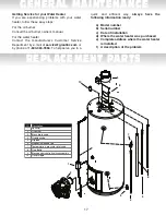
Page 17: ...y phone at 1 800 363 9354 To help serve you in a quick and efficient way always have the following information ready a Model number b Serial number c Date of installation d Where the water heater was purchased e Complete address where the water heater is installed f A description of the problem 1 2 3 4 5 7 8 6 9 10 I D Description 1 Aquastat 2 Oil burner 3 Brass drain valve 4 Overflow tube 5 Dip t...

Page 18: ...mage caused by not having the water heater installed adjacent to a free flowing drain in the event of water leakage 10 If the heater is operated at water temperatures exceeding the maximum setting of the operating or high limit control or the heater is not supplied with potable water free to circulate at all times 11 If the heater has experienced the effect of thermal expansion due to excessive pr...

Reviews: