IQ lock AUT, EL / EL DL, EM / EM DL, C / C DL, M / M DL
22
Installation
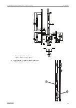
4.5.2 Mounting rod drive IQ AUT
X
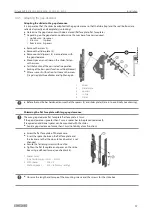
Insert the driving rod (1) (ID no. 152112) and screw
in place.
X
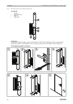
Wire the cables with connector according to the wir-
ing diagram and connect IQ AUT with the prepared
connector (2).
Connections
X1 - connection for power supply device, inputs and outputs
Connection
Wire colour
Signal
Function
x1.1
blue – BU
Voltage
supply
GND in
X1.3
red – RD
24 V (DC in)
X1.2
–
–
24 V DC
X1.5
brown – BN
Input
Release
X1.20
white – WH
Output 1
Output 1 (locked)
X1.21
grey – GY
Com
X1.22
pink – PK
Output 2
Unlocked
X1.21
grey – GY
Com
22
21
20
42
41
X1
X5
X4
5
2
3
1
41
42
43
2
1
Input
A potential-free contact (normally opened contact) must be connected to pins X1.2 and X1.5. If the contact is
activated, IQ AUT moves to the unlocked position where it remains for the hold-open time. The time starts once
the contact has been disconnected.
Output
IQ AUT has two outputs with the potential which is connected to pin X1.21. The output “unlocked” is closed when
the drive rod is in the unlocked position. Output 1 can be set (see Service menu).
X5 - connection for GEZE-BUS (e.g.: IO 320)
Connection
Wire colour
Signal
Function
X5.42
yellow – YE
GEZE-BUS
RS485-A
X5.41
green – GN
RS485-B


