background image

IQ lock AUT, EL / EL DL, EM / EM DL, C / C DL, M / M DL

16

Installation

4.4.4  Accessories in assembly


a

s

d

f

g

h

k

j

100

80

Ø5.5

Ø5.5

37

52

54

42

Ø18.7

Ø5.2

50

DM35

Ø15

60

Ø5.5

Ø5.2

20

20

10

80

Ø6

18

31

33

3

13

20

67

320

165

323

91

3

20

20

50

46

3

20

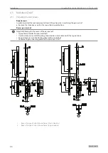
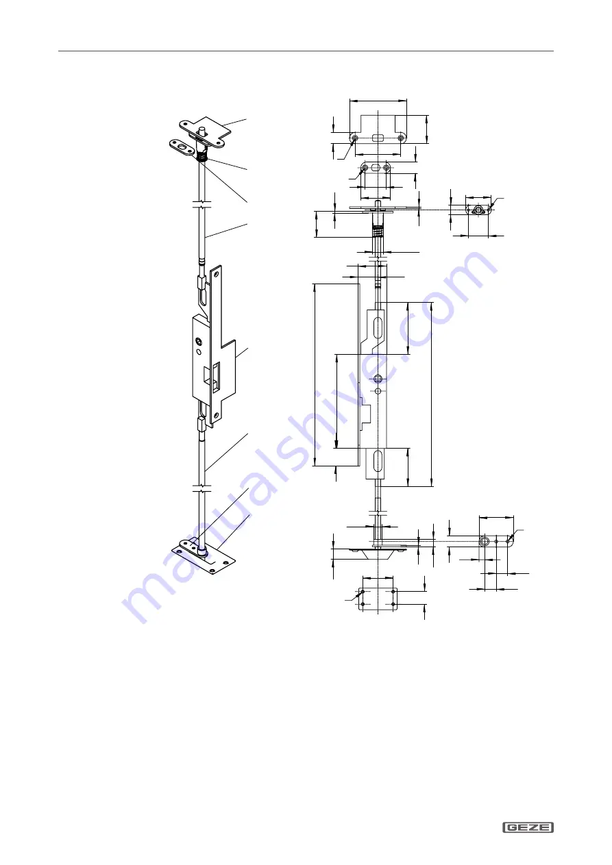
Lipped strike plate top (ID No. 133920)

Top lock top (ID No. 133922)

Strike plate top (ID No. 133921)

Round rod top (ID No. 133917)

Flanged face plate (DIN right, steel, ID No. 133909)

Round rod bottom (ID No. 133916)

Rod guide (ID No. 133918)

Bottom closing recess (ID No. 133919)

Summary of Contents for IQ lock AUT

Page 1: ...157719 02 IQ lock self locking panic locks for 1 and 2 leaf doors IQ lock AUT IQ lock EL IQ lock EL DL IQ lock EM IQ lock EM DL IQ lock C IQ lock C DL IQ lock M IQ lock M DL EN Installation manual ...

Page 2: ...rview of functions 7 3 2 Explanation of terms functions and properties 7 4 Installation 9 4 1 Lock for 1 leaf and 2 leaf doors door active leaf 9 4 2 Cable routing for IQ AUT IQ lock EL IQ lock EM and IQ lock C 10 4 3 Strike plate frame 10 4 4 Strike box passive leaf 2 leaf 12 4 5 Rod drive IQ AUT 20 4 6 Accessories 28 4 7 Sliding door fittings 39 4 8 Function checks after installation of the mech...

Page 3: ...leases the manufacturer from his statutory liability Abbreviations VB Solid leaf SB Width of flat face plate RR Tubular frame DM Backset SA Rod spacing DMA Backset adapter 1 Safety notices 1 1 Intended use Self locking panic locks are components used to lock emergency exit doors panic exit doors on rescue routes When self locking anti panic locks are used the technical data and environment conditi...

Page 4: ...exit doors closed Only spring supported door handles may be used In correlation with the specifications of German building regulation laws a lock of the VS type A in accordance with DIN EN 179 or DIN 1125 lock only for 1 leaf doors can also be used in the active leaf of a 2 leaf door if a the passive leaf lock is secured against maloperation and b the passage clearance of the active leaf is suffic...

Page 5: ... be modified in any way à à Lock and original strike plate 1 leaf as well as lock and original strike box 2 leaf form one unit Perfect func tion is only possible in combination à à If installation is faulty or improper all manufacturer guarantee and liability claims will be rendered invalid 1 7 Use of motor locks IQ lock EL IQ lock EL DL on fire and smoke protection doors GEZE motor locks IQ lock ...

Page 6: ...20 mm is implemented every time the door is closed The GEZE SecuLogic admission control for example regulates controlled admission In this case the bolt is retracted and the door can be passed through against the direction of emergency exit With the motor lock control MST 210 different release times can be set using a DIP switch Setting of the release time Opening time x 1 s Setting options for re...

Page 7: ...back contacts for lock states Optional sabotage monitoring or cylinder contact Can be used on the left and right Same installation dimensions for all IQ locks Backset 35 40 45 55 60 65 70 80 100 Distance 72 74 78 92 94 9 mm handle follower à à continuous à à divided Approval in accordance with EN 1125 Approval in accordance with EN 179 Approval in accordance with EN 14846 Approval in accordance wi...

Page 8: ...e commissioning and connection manual ID No 156328 Here the crossbar is retracted and the cross latches are unstable The door can be pulled or pushed open at any time by hand Exception In the event of a fire the door is locked completely after the door leaf has closed The motor lock is activated directly by the fire alarm system in this case Outside handle electrically engaged When the supply volt...

Page 9: ...g the construction phase Holding the door open with the crossbar extended is not permissible à à During work on the door leaf e g drilling and milling the lock must be removed from the door leaf à à The recess in the lock pocket must be carried out in compliance with the dimensional drawing below à à The pocket must be dimensioned in such a way that the lock can be inserted easily and screwed to t...

Page 10: ...ust be pulled from the lock side to the hinge side in the door leaf The following points must be heeded X X If possible lay an empty pipe with an inner diameter of at least 10 mm in the door leaf for the cable X X Establish the transition from the door leaf to the frame using a flexible drip loop X X Use the enclosed attachment material to connect the drip loop firmly to the door leaf and the door...

Page 11: ...oor 3 IQ lock 4 Strike plate 5 Clearance 3 7 mm 6 Cavities in the profile must be filled 7 Ensure entry areas are level 8 Lock does not enter process function not guaranteed 9 Strike plate 10 Control latch 11 Cross latches 12 Crossbar must run freely Lipped strike plate that can be shortened strike plate that can be shortened in width à à The clearance must be 3 7 mm between flat face plate and st...

Page 12: ...y latch of the lock must be activated from the same reference edge à à The distance between the strike box and the flat face plate must be between 3 mm and 7 mm à à Lock latch and auxiliary latch must be able to slide over a level surface without obstacle into the closing posi tion when the door closes à à Any profile ribs or profile grooves must be compensated à à There must not be any holes inde...

Page 13: ...6 mm tightening torque 3 1 Nm Preparation for installation long plate e g for GEZE panic bar ID No 119005 For tubular framed doors Distance Distance Strike box tubular frame doors short Strike box tubular frame doors long X X For all accessory variants for IQ lock DL for 2 leaf tubular framed doors see chapter 4 6 2 ...

Page 14: ...n dimensions solid leaf 1 1 Countersink screw M5 max 20 mm Preparation for installation long plate e g for GEZE panic bar ID No 119005 For solid leaf doors Distance Strike box solid leaf X X For all accessory variants for IQ lock DL for 2 leaf solid leaf doors see chapter 4 6 2 ...

Page 15: ... X X Calculating the rod length à à Tubular frame long strike box Lx x 110 mm à à Tubular frame short strike box Lx x 74 mm à à Solid leaf Lx x 42 mm X X Cut the rod to the calculated length Lx L X 110 mm 1 mm L X 74 mm 1 mm L X 42 mm 1 mm Cutting the round rod at the bottom to size X X Determine the distance Y see the drawing à à Bottom closing recess to centre of handle mandrel X X Calculating t...

Page 16: ...15 60 Ø5 5 Ø5 2 20 20 10 80 Ø6 18 31 33 3 13 20 67 320 165 323 91 3 20 20 50 46 3 20 1 Lipped strike plate top ID No 133920 2 Top lock top ID No 133922 3 Strike plate top ID No 133921 4 Round rod top ID No 133917 5 Flanged face plate DIN right steel ID No 133909 6 Round rod bottom ID No 133916 7 Rod guide ID No 133918 8 Bottom closing recess ID No 133919 ...

Page 17: ...e screw 1 again apply threadlocker and tighten again 4 5 1 Screw 2 Slider plate 3 Spacers 4 In line 5 Slider X X Before the Loctite has hardened ensure that the spacers 3 and slider plate 2 are in line vertically see drawing Shimming the flat face plate with large gap clearance The max gap clearance flat face plate flat face plate is 7 mm If the gap clearance is greater than 7 mm a spacer has to b...

Page 18: ...rt 2 Adjustable insert 3 Magnet 4 Strike plate Description With the adjustable strike plate a door can be adjusted so that it fits into the frame without clearance when closed The insert 2 can be adjusted in 0 8 mm steps and is held on the strike plate 4 by the magnet 3 Installing the adjustable strike plate 1 2 3 4 5 6 7 ...

Page 19: ...Q lock AUT EL EL DL EM EM DL C C DL M M DL 19 Installation Adjustment range latch cut out Adjustment L mm Latch cut out mm Adjustment L mm Latch cut out mm 0 14 7 max 1 6 13 1 0 8 13 9 3 2 11 5 2 4 12 3 ...

Page 20: ...ar top and bottom Recess passive leaf Note the following for the recess of the passive leaf à à Type of door tubular frame or solid leaf à à Use the dimensions and drill spacing shown below in accordance with the type of door à à Recess dimensions for the flat face plate width on solid leaf à à Cable routing must be designated for the rod drive IQ AUT 1 Recess for type of door Tubular frame short ...

Page 21: ... DL C C DL M M DL 21 Installation 3 Recess for type of door Solid leaf depth of recess according to backset Milling Milling Bore holes Bore holes X X Install strike box 1 flanged face plate strike box 2 and bottom round rod 1 2 ...

Page 22: ...t 1 locked X1 21 grey GY Com X1 22 pink PK Output 2 Unlocked X1 21 grey GY Com 22 21 20 42 41 X1 X5 X4 5 2 3 1 41 42 43 2 1 Input A potential free contact normally opened contact must be connected to pins X1 2 and X1 5 If the contact is activated IQ AUT moves to the unlocked position where it remains for the hold open time The time starts once the contact has been disconnected Output IQ AUT has tw...

Page 23: ...witched on in the first and last device 43 ON OFF 22 x1 21 20 5 2 3 1 41 42 2 1 X4 1 Fitting IQ AUT X X Insert the rod drive IQ AUT 1 into the recess X X Make sure that the adapter rod 3 is inserted com pletely into the funnel The adapter rod 3 must be completely flush to the end stop so that the hexagon socket screw 2 can be fixed through the elongated hole X X Tighten the hexagon socket screw 2 ...

Page 24: ... backset a corresponding number of backset adapters 4 must be used see table Tubular frame type of door Backset Number 35 1 40 2 45 3 55 5 60 6 70 8 Solid leaf type of door Backset Number 55 0 60 1 65 0 70 1 80 3 100 7 X X Make sure that the lugs 5 of the backset adapter 4 are completely latched in place ...

Page 25: ... IQ AUT must be able to move vertically in the elongated holes due to its own weight X X Screw tow outer screws 3 on the door and tighten them Heed the different screw length depending on the number of backset adapters Number of backset adapters Screw pack ID No Countersunk screws ISO 10642 A2 0 152717 M5 10 1 152718 M5 16 2 152719 M5 20 3 152720 M5 25 5 152721 M5 35 6 161997 M5 40 7 152722 M5 45 ...

Page 26: ... round rod top roughly to size to be able to insert the round rod top straight into the profile X X Screw the round rod top into IQ AUT X X Mount the top lock X X Mark the round rod top for correct length X X Screw the round rod top out of the profile again X X Shorten the round rod top to the marking and insert plug into the upper round rod top X X Screw the round rod top back in ...

Page 27: ...nic door fitting to lock in the frame and move to end stop position à à The panic door fitting must not be activated locked X X Tighten the three middle screws Final check X X Push the panic bar down X X Make sure that the panic door fitting unlocks and locks safely see chapter 6 Maintenance ...

Page 28: ... mm 168588 Lipped strike plate adjustable RR DIN left 24 270 4 mm 168587 Lipped strike plate adjustable RR DIN right 24 270 4 mm 122628 U strike plate RR DIN left right 49 270 9 mm 103657 Angled strike plate short VB DIN left right 20 235 8 mm standard scope of supply with distance 72 122627 Angled strike plate long VB DIN left right 20 270 20 mm 103658 Lipped strike plate VB DIN left right 50 235...

Page 29: ...10 20 235 8 20 2 5 75 5 56 6 123 123 20 20 20 17 3 2 7 2 5 270 81 12 56 12 104 5 104 5 3 2 7 50 62 5 13 56 235 13 62 5 209 235 100 27 3 25 8 20 50 13 62 5 28 8 20 57 209 235 100 27 4 1 28 3 103657 122627 103658 139167 DIN left 139166 DIN right 169758 DIN left 169757 DIN right 13 4 1 62 5 30 8 24 5 30 59 209 235 100 27 Ø6 5 A A 75 5 32 40 50 56 209 235 0 2 0 2 0 2 235 10 27 209 104 5 13 3 75 5 9 0 ...

Page 30: ... 210 246 12 18 24 16 16 16 28 28 122629 152999 161535 4 6 2 IQ lock DL 2 leaf Flat face plate lock active leaf Product description Type of door Description DIN direction W H D Flat face plate RR DIN left right 22 285 3 mm Flat face plate RR DIN left right 24 270 3 mm Flat face plate RR DIN left right 28 270 3 mm Flat face plate VB DIN left right 20 235 3 mm Flat face plate VB DIN left right 24 235...

Page 31: ... RR DIN left 24 320 3 mm 133909 Flanged face plate RR DIN right 24 320 3 mm 161536 Flanged face plate RR DIN left 28 320 3 mm 161537 Flanged face plate RR DIN right 28 320 3 mm 133912 Flanged face plate VB DIN left 20 320 3 mm 133911 Flanged face plate VB DIN right 20 320 3 mm 148842 Flanged face plate VB DIN left 25 5 320 3 mm FN9 148841 Flanged face plate VB DIN right 25 5 320 3 mm FN9 148844 Fl...

Page 32: ... 0 15 0 15 93 22 5 2 5 20 10 83 110 320 FN 56 110 12 296 FN 9 143 0 15 296 0 2 0 2 3 1x45 93 22 5 2 5 20 10 83 110 320 FN 56 110 12 296 FN 24 0 2 143 0 2 0 15 3 0 15 1x45 148842 DIN left 148841 DIN right 148844 DIN left 148843 DIN right 148958 DIN left 148957 DIN right 168663 DIN left 168662 DIN right 169760 DIN left 169659 DIN right ...

Page 33: ... mm 122629 152999 161535 Support strike box passive leaf ID No Product description Type of door Description DIN direction W H D 161365 Support strike box RR DIN left right 24 285 3 mm 133914 Support strike box RR DIN left right 24 320 3 mm for profiles with 6 mm U flat face plate 153000 Support strike box RR DIN left right 28 320 3 mm 161538 Support strike box RR DIN left right 28 320 1 5 mm 13391...

Page 34: ...545 3 mm 153001 Flat face plate IQ AUT RR DIN left right 28 545 3 mm 152108 Flat face plate IQ AUT VB DIN left right 20 545 3 mm 152110 Flat face plate IQ AUT VB DIN left right 24 545 3 mm 164244 152111 153001 152108 152110 Supports IQ AUT passive leaf ID No Product description Description DIN direction W H D 153004 Support IQ AUT DIN left right 24 545 3 mm 161539 Support IQ AUT DIN left right 28 ...

Page 35: ...IQ lock AUT EL EL DL EM EM DL C C DL M M DL 35 Installation 4 6 3 Accessories Rod locking Manual locking devices 156705 161530 Top lock top 156726 157391 ...

Page 36: ... EM EM DL C C DL M M DL 36 Installation Top lock supports Top lock supports for strike plates 161528 161534 161533 161525 Rod guides Top lock Round rod guide Planet rod guide Flat strike plates 133918 156707 133921 164102 ...

Page 37: ... DL C C DL M M DL 37 Installation Rod locking top Locking bolts Length 1000 mm 156709 133916 134955 Length 1500 mm 156710 Length 2000 mm 156711 Length 2500 mm 156722 Top lock solid leaf Lipped strike plates 161532 133920 156724 ...

Page 38: ... Top lock tubular frame Lipped strike plates 161978 DIN left 162323 DIN left 162322 DIN left right 162324 DIN left right 162310 DIN left right 162311 DIN left right 161977 DIN right 161980 DIN right IQ AUT Driving rods Length 190 mm 152112 Length 275 mm 178355 ...

Page 39: ...nic exit device X X Ensure that the door can be opened freely when the panic exit device is operated à à In the case of doors that cannot be opened wider than 90 a Class 2 panic exit device normal projection has to be used à à Check whether glass elements at panic exit devices are equipped with safety glass or laminated safety glass à à Panic exit devices are not designed for use on double action ...

Page 40: ...ce must be used for unlocking X X Make sure that the drive rod is not blocked Wh_UL2_ON Bar_L_ON The Hall sensor at the locked position of the drive rod is active in the unlocked state This fault is only triggered in the unlocked state à à Attempted manipulation Some has tried to gener ate a locked signal à à The bar lock Hall sensor is defective X X Check whether the door has been manipulated X X...

Page 41: ... control X X Reset the activation and start activation of the lock again fault message will go out if successful Power supply cable defective Lock is not being sup plied with 24 V DC X X Check continuity and replace the power supply cable of the lock if necessary Control is not being supplied with 24 V DC In the event of attempt ed manipulation the bolt of the auxiliary latch is closed and can no ...

Page 42: ...tivation of the night latch function using the key Door handle is jammed in activated position or Handle return spring is broken The door handle does not return to its initial position after activation and there is no locking signal given X X Loosen the screws lubricate the handle guide correct fastening or X X Replace the lock Auxiliary latch is not activated Lock does not lock when the door is c...

Page 43: ...lock when the door is closed X X Check the clearance of the door leaf Bolt shoots out again imme diately after the door has been opened Door handle has not been pressed down completely or Auxiliary latch is jammed in activated position Slider is not held in perma nently unlocked position door cannot close and be locked properly X X Press the handle down as far as it will go X X Check the tension f...

Page 44: ...sure and record the operating forces required to release the panic exit device emergency exit lock à à Ensure that the operating forces have not changed substantially in comparison to the operating forces record ed during initial commissioning à à Ensure that bolt heads or keepers are not blocked or clogged up à à Ensure that the panic exit device has been lubricated according to the manufacturer ...

Page 45: ...ock AUT Release ability passed 80 N without load 200 N with load Permanent functionality with regard to release ability in terms of ageing and loss of quality of doors on escape routes passed 200 000 cycles 80 N Usage category Permanent function Weight of door Fire smoke protection Safety Corrosion behaviour Protection against bur glary Projection of the sliding door fitting Type of activation App...

Page 46: ...bility passed 80 N without load 200 N with load Permanent functionality with regard to release ability in terms of ageing and loss of quality of doors on escape routes passed 200 000 cycles Usage category Permanent function Weight of door Fire smoke protection Safety Corrosion behaviour Protection against bur glary Projection of the sliding door fitting Type of activation Application area 3 7 7 B ...

Page 47: ...nent function and latch load Door weight and clos ing force Suitability for use on fire smoke protection doors Safety Corrosion resistance temperature and humidity Protective effect and drilling resistance Protective effect with regard to electrical function Protective effect with regard to electrical manipulation 3 x 8 E 0 M 5 0 3 7 2 Consistency of performance certificate in accordance with EN 1...

Page 48: ...IQ lock AUT EL EL DL EM EM DL C C DL M M DL 48 Annex ...

Page 49: ...IQ lock AUT EL EL DL EM EM DL C C DL M M DL 49 Annex 7 3 Consistency of performance certificate in accordance with EN 179 ...

Page 50: ...IQ lock AUT EL EL DL EM EM DL C C DL M M DL 50 Annex ...

Page 51: ...IQ lock AUT EL EL DL EM EM DL C C DL M M DL 51 ...

Page 52: ...com cn France GEZE France S A R L E Mail france fr geze com www geze fr Hungary GEZE Hungary Kft E Mail office hungary geze com www geze hu Iberia GEZE Iberia S R L E Mail info geze es www geze es India GEZE India Private Ltd E Mail office india geze com www geze in Italy GEZE Italia S r l E Mail italia it geze com www geze it GEZE Engineering Roma S r l E Mail roma geze biz www geze it Poland GEZ...

Reviews: