IQ lock AUT, EL / EL DL, EM / EM DL, C / C DL, M / M DL
17
Installation
4.4.5 Adapting the gap clearance
Adapting the slider to the gap clearance
It is imperative that the slider be adapted to the gap clearance so that the tube (top) and the rod (bottom) are
retracted correctly and completely (unlocking).
X
Determine the gap clearance with doors closed (flat face plate-flat face plate).
X
Depending on the gap clearance, determine the number of spacers required:
à
up to 4 mm: no spacer
à
4–6 mm:
1 spacer
à
from 6 mm: 2 spacers
X
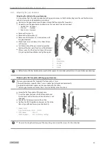
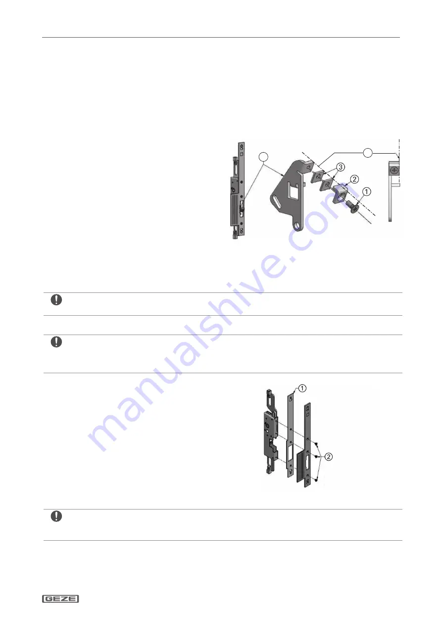
Remove the screw (1).
X
Remove the slider plate (2).
X
Remove or add spacers (3) in accordance with
the gap clearance.
X
Mount spacers and slider on the slider, fasten
with a screw.
X
Test the function of the passive leaf in operation
(locking of the bars, panic function with both leaves).
X
After a successful function test loosen the screw
(1) again, apply threadlocker and tighten again.
4
5
1
Screw
2
Slider plate
3
Spacers
4
In line
5
Slider
X
Before the Loctite has hardened, ensure that the spacers (3) and slider plate (2) are in line vertically (see drawing).
Shimming the flat face plate with large gap clearance
The max. gap clearance flat face plate-flat face plate is 7 mm.
If the gap clearance is greater than 7 mm, a spacer has to be placed underneath.
If required an additional spacer can be mounted with the slider.
X
Avoid a gap clearance of more than 7 mm (no liability at malfunction).
X
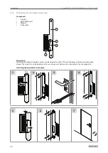
Screw the flat face plate off the lockcase.
X
Insert the spacer between the flat face plate and
the lockcase so that the door-to-lock backset is not
changed.
X
Secure the fastening screws with Loctite.
X
Tighten the flat face plate and spacer on the strike
box using a defined torque (see chapter 4.4).
1 Spacer 2 mm
(only for door gap >7 mm – 9 mm)
2 With spacer:
M4 × 8
Without spacer:
M4 × 6 (factory setting)
X
Observe the length and torque of the mounting screws and the screws for the strike box.


