IQ lock AUT, EL / EL DL, EM / EM DL, C / C DL, M / M DL
10
Installation
4.2 Cable routing for IQ AUT, IQ lock EL, IQ lock EM and IQ lock C
X
When shortening the power supply cable, consider that a longer power supply cable may be required for in-
stalling and removing the lock. We recommend a minimum of 15 cm in addition in order to release and insert
the plug without any problems.
X
Make sure that the drip loop has an interior diameter of at least 10 mm and that the length corresponds to the
degree of opening of the door. We recommend GEZE drip loops.
Cable loops for inspection
X
Note the dimensions of the coupling connector.
X
Round off the corners and edges round which the cable has to be routed to prevent damage to the cable.
With flat door designs, the cable exit for the GEZE IQ lock EL and IQ lock EM is horizontal to the rear. This results in
the depth of the recess from the dimension for the lock box depth plus approx. 25 mm for a cable loop.
With tubular frame door designs, the cable exit for the GEZE IQ lock EL and IQ lock EM is vertical upwards. In this
case, the cable loop must be pushed into a suitable profile chamber.
Cable routing
The power supply cable for GEZE panic locks must be pulled from the lock side to the hinge side
in the door leaf.
The following points must be heeded:
X
If possible, lay an empty pipe with an inner diameter of at least 10 mm in the door leaf for the cable.
X
Establish the transition from the door leaf to the frame using a flexible drip loop.
X
Use the enclosed attachment material to connect the drip loop firmly to the door leaf and the door frame.
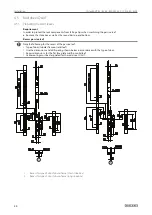
4.3 Strike plate (frame)
There is a suitable strike plate tested in accordance with EN 179 and EN 1125 enclosed with every lock. For cut-
outs in door frames on doors which are not subject to these standards, please note the following information.
a
s
s
d
f
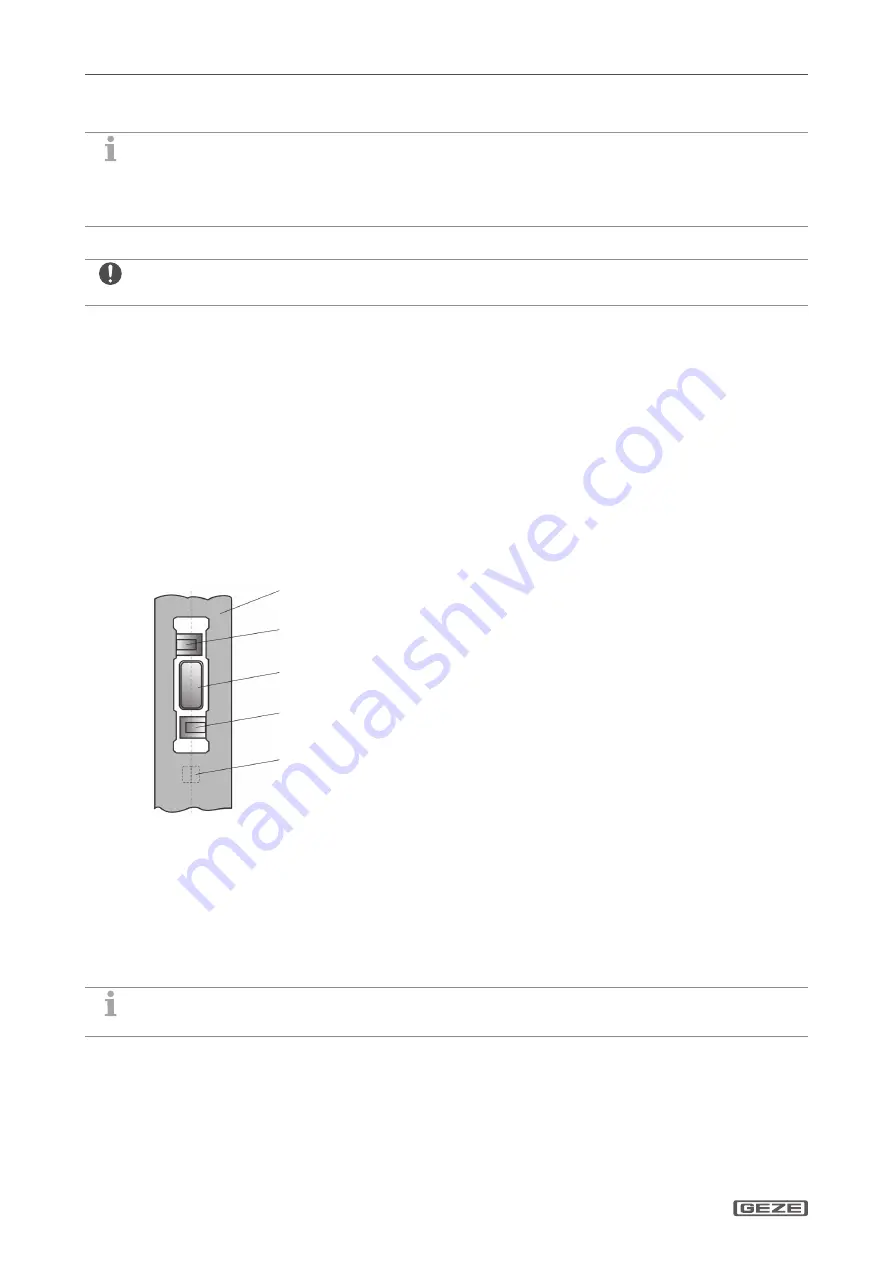
1
Strike plate
2
Cross latch
3
Crossbar
4
Auxiliary latch
à
Lock latch and auxiliary latch of the lock must be activated from the same reference edge.
à
The distance between the strike plate and the flat face plate must be between 3 mm and 7 mm.
à
Lock latch and auxiliary latch must be able to slide over a level surface without obstacle into the closing posi-
tion when the door closes:
à
Any profile ribs or profile grooves must be compensated by the strike plate.
à
There must not be any holes, indentations or unevenness in the entry area of the auxiliary catch:
X
When mounting the strike plate ensure that the auxiliary catch cannot latch into the recess for the cross latch/
crossbar!
Special strike plates on request


