background image


DVR Configurations


171

7

7.3  Remote Monitoring with Multi View 

You can use the Multi View to monitor and manage the camera.  

Note: 

Multi View is not supported by GV-VMS.


7.3.1  Connecting to the IP Camera 

1.  On the Multi View window, click the 

Edit Host

 button. The Edit Host window appears.  

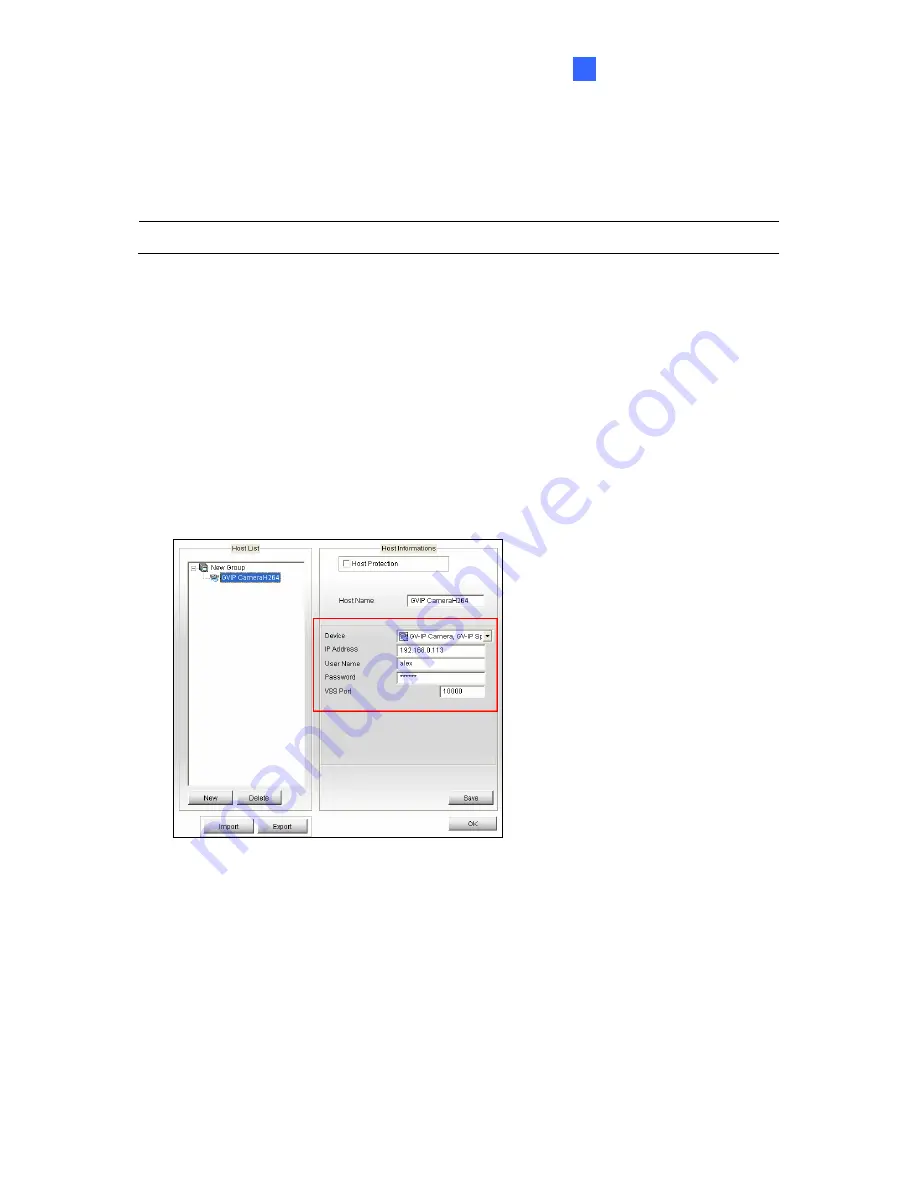
2.  To create a host, click the 

New

 button. You need to create a group before creating a 

host. 

3. Select 

GV-IP Camera

GV-IP Speed Dome

 from the Device drop-down list. Type the 

host name, IP address, user name and password of the camera. Modify the default VSS 
port 

10000

 if necessary. 


Figure 7-11 

4. Click 

Save

 to establish connection. 


For details on the Multi View functions, see “Multi View Viewer”, 

Remote Viewing, DVR 

User’s Manual

 on the Surveillance System Software DVD. 


Summary of Contents for GV-Fisheye

Page 1: ...Before attempting to connect or operate this product please read these instructions carefully and save this manual for future use User s Manual GV Fisheye IP Camera H 264 FETIV30 B ...

Page 2: ...ssumed for incidental or consequential damages arising from the use of the information or products contained herein Features and specifications are subject to change without notice Note No memory card slot or local storage function for Argentina GeoVision Inc 9F No 246 Sec 1 Neihu Rd Neihu District Taipei Taiwan Tel 886 2 8797 8377 Fax 886 2 8797 8335 http www geovision com tw Trademarks used in t...

Page 3: ...4301 GV FE2302 GV FE3402 3403 Fisheye Camera GV FE5302 5303 GV FER3402 3403 GV FER521 Fisheye Rugged Camera GV FER5302 5303 V3 0 Note 1 To upgrade the camera firmware from V2 07 or earlier to the latest version back up the files in the camera s memory card first before the upgrade and it is required to re format the memory card after the upgrade 2 With future firmware version GV Fisheye IP Camera ...

Page 4: ... 3403 5302 5303 15 1 6 Installation 18 1 6 1 Hard Ceiling Mount 19 1 6 2 In Ceiling Mount 23 1 6 3 Standard Wall Mount and Ground Mount 26 1 6 4 Ground Mount 26 1 7 Connecting the GV Fisheye Camera 27 1 7 1 GV FE2301 421 4301 521 27 1 7 2 GV FER521 29 1 7 3 GV FE2302 3402 3403 5302 5303 30 1 7 4 Connecting PoE Converter and IR LED Ring for GV FE3403 5303 31 1 7 5 GV FER3402 3403 5302 5303 34 Chapt...

Page 5: ...nd Audio Configuration 66 3 2 11 Remote Configuration 68 3 2 12 Camera Name Display 68 3 2 13 Image Enhancement 68 3 2 14 I O Control 69 3 2 15 Visual Automation 70 3 2 16 Network Status 71 Chapter 4 Administrator Mode 72 4 1 Video Motion 74 4 1 1 Video Settings 75 4 1 2 Motion Detection 81 4 1 3 Privacy Mask 83 4 1 4 Text Overlay 84 4 1 5 Tampering Alarm 85 4 1 6 Visual Automation 87 4 2 I O Cont...

Page 6: ... 4 UMTS Settings 118 4 7 5 IP Filtering 120 4 7 6 SNMP Setting 121 4 8 Management 122 4 8 1 Date and Time Settings 122 4 8 2 Storage Settings 124 4 8 3 User Account 129 4 8 4 Log Information 130 4 8 5 Tools 132 4 8 6 Language 134 Chapter 5 Recording and Playback 135 5 1 Recording 135 5 2 Playback 136 5 2 1 Playback from the Memory Card 136 5 2 2 Playback over Network 141 5 2 3 Access to the Record...

Page 7: ...Watermark Proof 156 6 5 3 The Watermark Proof Window 157 6 6 Downloading Videos from the Micro SD Card 158 6 6 1 Installing the GV SDCardSync Utility 158 6 6 2 The GV SDCardSync Utility Window 161 Chapter 7 DVR Configurations 162 7 1 Setting Up IP Cameras on GV System 164 7 1 1 Customizing the Basic Settings on GV System 167 7 2 Setting Up IP Cameras on GV VMS 168 7 3 Remote Monitoring with Multi ...

Page 8: ...l Support 181 C The Supported Mobile Broadband Devices 182 D The CGI Command 183 E Supported Firmware for Flash Memory 184 Specifications 185 Camera 185 Optics Lens 186 Operation 188 Network 189 Mechanical 190 General 190 Power over Ethernet 194 Web Interface 195 Application 195 ...

Page 9: ...System GeoVision Analog and Digital Video Recording Software The GV System also refers to Multicam System GV NVR System GV Hybrid DVR System and GV DVR System at the same time GV VMS GeoVision Video Management System for IP cameras ...

Page 10: ...ystem GV VMS 1 By default the images are recorded to the memory card inserted in the GV Fisheye IP Camera 2 Once the camera is connected to the GV System GV VMS the resolution set on the GV System GV VMS will override the resolution set on the camera s Web interface You can only change the resolution settings through the Web interface when the connection to the GV System GV VMS is interrupted ...

Page 11: ... for such causes The stored data can be lost if the memory card is not accessed for a long period of time Back up your data periodically if you seldom access the memory card Memory cards are expendable and their durability varies according to the conditions of the installed site and how they are used Back up your data regularly and replace the memory card annually To avoid power outage it is highl...

Page 12: ...pter 1 The USB hard drive must be of 2 5 or 3 5 version 2 0 or above 2 The USB hard drive s storage capacity must not exceed 2TB 3 USB flash drives and USB hubs are not supported 4 External power supply is required for the USB hard drive 5 To connect a GV WiFi Adapter make sure it is connected before the camera is powered on ...

Page 13: ...The camera is set up above the junction box to prevent water from entering the camera along the cables 2 Any PoE power audio and I O cables are waterproofed using waterproof silicon rubber or the like 3 The screws are tightened and the cover is in place after opening the camera cover ...

Page 14: ...conceal the gel bag in camera within 2 minutes of exposing to open air When installing GV FE indoor models be sure that Keep the indoor camera shielded from rain and moisture When installing GV FE or GV FER models with IR LED rings be sure that An operating IR LED ring may reach high temperatures of up to 60 C 140 F Disconnect the power supply and allow the IR LED ring to cool down before handling...

Page 15: ... detection privacy mask and alert notification through the Web interface In addition GV Fisheye IP Camera seamlessly integrates with the GV System GV VMS providing advanced monitoring and video management features The following GV Fisheye Cameras are available Models Type Description GV FE2301 421 4301 521 2 MP 4 MP 5 MP GV FE2302 3402 5302 2 MP 3 MP WDR Pro 5 MP GV FE3403 5303 Indoor 3 MP WDR Pro...

Page 16: ...302 5303 GV FER521 5302 5303 1 2 5 progressive scan CMOS GV FE3402 3403 GV FER3402 3403 1 3 2 progressive scan CMOS Dual streams from H 264 or MJPEG Video Compression Camera Model Video Compression GV FE2301 2302 GV FE3402 3403 GV FE421 GV FE4301 GV FE521 GV FER3402 3403 GV FER521 GV FER5302 5303 H 264 MJPEG ...

Page 17: ... GV FE5521 GV FER521 Electronic GV FE2302 GV FE3402 3403 GV FE5302 5303 GV FER3402 3403 GV FER5302 5303 Removable IR cut filter IR LED with effective distance up to 10 m 32 81 ft GV FE3403 5303 and GV FER3403 5303 Wide Dynamic Range WDR for GV FE2302 5302 5303 and GV FER5302 5303 Wide Dynamic Range Pro WDR Pro for GV FE3402 3403 and GV FER3402 3403 Defog IP66 rating GV FER521 only IP67 rating GV F...

Page 18: ...403 5302 5303 only One sensor input and alarm output GV FE2301 421 4301 521 only Digital Object Tracking Virtual PTZ function Auto Pan function Provides 360 and 180 panorama view No mechanical moving parts Different angle of view controllable by multiple users at the same time Playback from any view angle and zoom level Privacy mask Visual automation Tampering alarm Text overlay 31 languages on We...

Page 19: ... Mount x 3 Screw In Ceiling Mount x 3 Torx Wrench Plastic Screw Anchor x 3 Installation Sticker GV NVR Quick Start Guide For GV FE421 521 2301 4301 only 3 Pin or 2 Pin Terminal Block DC 12V Power Adapter For GV FER521 only Cable Connector Silica Gel Bag and Adhesive Tape x 2 GV IPCAM H 264 Software DVD GV Fisheye IP Camera Quick Start Guide GV NVR Software DVD GV NVR Quick Start Guide ...

Page 20: ...sheye Camera Support Bracket x 3 Camera Cover Hard Ceiling Mount Camera Cover In Ceiling Mount Screw Hard Ceiling Mount x 3 Screw In Ceiling Mount x 3 Torx Wrench Plastic Screw Anchor x 3 Mini USB Extension Cable IR LED Ring GV FE3403 5303 only ...

Page 21: ... Y cable 1 RJ 45 cable and 3 PoE Screws GV FE3403 5303 only Installation Sticker Power Adapter GV IPCAM H 264 Software DVD GV Fisheye IP Dome Hardware Installation Guide GV NVR Software DVD GV NVR Quick Start Guide Note The power adapter can be excluded upon request ...

Page 22: ...Fisheye Camera Support Bracket x 3 Camera Cover Hard Ceiling Mount Camera Cover In Ceiling Mount Screw Hard Ceiling Mount x 3 Screw In Ceiling Mount x 3 Torx Wrench Plastic Screw Anchor x 3 IR LED Ring GV FER3403 5303 only Waterproof Rubber ...

Page 23: ...V FER3403 5303 only Installation Sticker Silica Gel Bag and Adhesive Tape x 2 Cable Connector Power Adapter DC 12V 1 25A GV IPCAM H 264 Software DVD GV Fisheye IP Dome Hardware Installation Guide GV NVR Software DVD GV NVR Quick Start Guide Note The power adapter can be excluded upon request ...

Page 24: ...oogle Chrome Safari Note 1 If you are using Microsoft Internet Explorer 8 0 or later additional settings are required Refer to Settings for Internet Explorer 8 or later in Appendix A 2 When using non IE browsers a The following functions are not supported Motion Detection Tampering Alarm Visual Automation Text Overlay and Two Way Audio To see the functions available on live view windows using non ...

Page 25: ...t Accessories Installation Guide online GV WiFi Adapter The GV WiFi Adapter is a plug and play device that provides WiFi connectivity to GV IP Cameras through a mini USB port This product complies with IEEE 802 11 b g n Draft 3 0 standards for wireless networking GV POE Switch The GV POE Switch is designed to provide power along with network connection for IP devices The GV POE Switch is available...

Page 26: ...FER521 Note For GV FER521 a silica gel bag is attached to the inside of the camera cover The silica gel loses effectiveness after you open the camera cover To prevent the lens from fogging up it is highly recommended to replace the silica gel bag every time you open the camera To replace the silica gel bag use the supplied adhesive tape to attach a new silica gel bag and fasten the camera cover wi...

Page 27: ...r 3 Microphone Receives the sound from the camera 4 Default Button Resets all configurations to default factory settings See 6 3 Restoring to Factory Default Settings 5 Micro SD Card Slot Inserts a micro SD SDHC memory card to store recorded data 6 Network status LED Indicates the network status 7 Power status LED Indicates whether the camera is powered on or off 8 System status LED Indicates whet...

Page 28: ...ully or not 5 LAN PoE Connects to a 10 100 Ethernet or PoE 6 Terminal Block Connects to power 7 Default Button Resets all configurations to default factory settings See 6 3 Restoring to Factory Default Settings 8 Audio Out Connects to an external speaker for broadcast 9 Micro SD Card Slot Inserts a micro SD SDHC memory card to store recorded data 10 Mini USB Slot Connects to a GV WiFi Adapter or a...

Page 29: ...mputer 3 Microphone Receives the sound from the camera 4 LEDs See the table below for details 5 Default Button Resets all configurations to default factory settings See 6 3 Restoring to Factory Default Settings 6 Micro SD Card Slot Inserts a micro SD SDHC memory card to store recorded data 7 Terminal Block Connects to power Note SDXC and UHS I card types are not supported ...

Page 30: ... to replace the silica gel bag every time you open the camera To replace the silica gel bag use the supplied adhesive tape to attach a new silica gel bag and fasten the camera cover within 2 minutes of opening the silica gel bag package LED Indicators 1 2 3 Figure 1 5 No Name Function 1 Link Turns on when network is connected 2 ACT Turns on when data are being transmitted or received 3 Status Turn...

Page 31: ...Introduction 17 1 PoE Cable For GV FER3402 3403 5302 5303 the PoE connector may be one of the following types Type 1 42 8 mm 1 7 Ø19 6 0 8 Type 2 58 5 mm 2 3 Ø28 2 1 1 ...

Page 32: ...strength to support the fisheye camera Note To re focus your camera follow the instruction below However it is only recommended to re focus your camera when the live view is blurry GV FE421 521 2301 4301 and GV FER521 Loosen the indicated screw and manually adjust the focus ring with your fingers Focus Ring Screws GV FE2302 3402 3403 5302 5303 and GV FER3402 3403 5302 5303 Manually adjust the focu...

Page 33: ...of the screws To install GV Fisheye Camera with PoE converter GV FE3403 5303 drill the 3 holes and the rectangle block indicated as PoE Converter to install GV Fisheye Camera only with the IR LED ring GV FE3403 5303 and GV FER3403 5303 drill the 3 holes indicated as Device and the circle indicated as IR Figure 1 6 2 At the 3 red dots drill a hole slightly smaller than the plastic screw anchors pro...

Page 34: ...02 5303 install the supplied cable connector to waterproof the cable You should have 2 components Figure 1 8 a Prepare an internet cable with the RJ 45 connector on one end only b Connect the internet cable to the camera data cable c Slide in the components through the end of the Internet cable without RJ 45 connector as shown below Figure 1 9 ...

Page 35: ...tightly to waterproof the cable 6 For GV Fisheye Camera that does not come with an IR LED ring place the camera cover for hard ceiling mount on top of the camera and tighten the screws with the supplied torx wrench Figure 1 11 7 For GV Fisheye Camera with an IR LED ring follow the steps below to secure the IR LED ring to the camera A Secure the safety lock to the camera Then secure the camera cove...

Page 36: ... of the camera and tighten the screws with the torx wrench provided Figure 1 13 Caution An operating IR LED ring may reach high temperatures Disconnect the power supply and allow the IR LED ring to cool down before handling the device ...

Page 37: ...he ceiling board to be between 0 5 3 0 cm 0 2 1 18 in thick Figure 1 14 Note In ceiling mount is not applicable to the models with IR LED ring GV FE3403 5303 and GV FER3403 5303 1 Place the installation sticker on the ceiling board and cut the circle part out of the ceiling To install GV FE2302 3402 5302 and GV FER3402 5302 drill the 3 holes indicated as Device Figure 1 15 ...

Page 38: ...using the in ceiling mount screws provided Figure 1 16 3 For outdoor GV Fisheye Cameras GV FER3402 521 5302 install the supplied cable connector to waterproof the cable Refer to step 5 in 1 6 1 Hard Ceiling Mount for details 4 Place the fisheye camera into the ceiling opening as shown below Figure 1 17 ...

Page 39: ... From the front side of the camera tighten the screws Figure 1 19 7 Connect the camera with power network and other wires For details see 1 7 Connecting the GV Fisheye Camera 8 Place the camera cover for in ceiling mount on top of the camera and tighten the 3 screws or just put on the in ceiling cover if it does not contain screws Figure 1 20 ...

Page 40: ...an excellent overview Or ensure the camera is focused on the most important areas of the room as directly as possible to have the desired detailed recognition 2 Orientate your the camera using the printed text TOP on the camera or the installation sticker 1 6 4 Ground Mount For ground mount simply install the hard ceiling cover and place the camera on a flat surface such as a conference table Figu...

Page 41: ...ta cable that allows you to connect to the power and any I O devices Ethernet PoE Digital Output Red Digital Input Brown AC 24V DC Orange GND Black AC 24V DC Yellow Figure 1 23 Wire Definition No Wire Color Definition 1 Yellow AC 24V DC 12V 2 Orange AC 24V DC 12V 3 Brown Digital Input 4 Red Digital Output 5 Black GND ...

Page 42: ... pin terminal block provided 1 Insert the yellow wire to the pin on the right side of the terminal block and the orange wire to the pin on the left side of the terminal block 2 Use a small flat tip screwdriver to secure the screws above the pins Figure 1 24 3 Connect the DC 12V Power Adapter to the Terminal Block DC 12V Power Adapter Terminal Block Figure 1 25 Note 1 A DC 12V power adapter has bee...

Page 43: ...omes with a PoE cable that allows you to connect to the power and network through a PoE adaptor See Power over Ethernet in Specifications later in this manual before purchasing a PoE adapter Note Digital input and output are not supported in GV FER521 ...

Page 44: ...3403 5303 A PoE converter allows the camera to be connected to a PoE switch thus supplied with network and power over a network cable and also supplies power to IR LED ring For installation steps see 1 7 4 Connecting PoE Converter and IR LED Ring for GV FE3403 5303 3 Optionally insert a micro SD card SD SDHC version 2 0 only Class 10 4 Optionally connect an external speaker 5 Optionally connect a ...

Page 45: ... optional accessory Figure 1 27 1 Connect the PoE converter to a PoE switch with a standard network cable Use the RJ 45 connector on the left Note 1 Due to limited space inside the PoE converter use a standard network cable without the rubber boot 2 The camera will not work if you connect the wrong devices to the two RJ 45 connectors on the PoE converter 2 Connect PoE Converter and the camera with...

Page 46: ...e camera and the other one to the IR LED ring IMPORTANT It is advised to shorten the IR LED ring s wire to approximately 20 cm for it to fit inside the PoE converter 20cm Figure 1 28 4 Secure the camera to the PoE converter with the supplied screws Figure 1 29 ...

Page 47: ...Introduction 33 1 5 Secure the PoE converter to the ceiling with 3 self prepared screws Figure 1 30 ...

Page 48: ... one of the following A Power adapter see Assembling the Power Adapter later in this section B Power over Ethernet PoE connect the camera to a PoE switch with a standard network cable to supply power and network 3 Optionally insert a micro SD card SD SDHC version 2 0 only Class 10 4 Secure the camera cover with the supplied torx wrench ...

Page 49: ...rt the power cable into the supplied female terminal block as illustrated and plug it into the terminal block connector in the camera Figure 1 34 3 Insert the power wires at the other end into the male terminal block as illustrated and plug it to the power adapter DC 12V Power Adapter Terminal Block Female Terminal Block Connect to Camera Male Female Figure 1 35 ...

Page 50: ...ng the Data Cable Use the Power over Ethernet PoE function The power will be provided over the network cable 3 You can now access the Web interface of the camera If the camera is installed in a LAN without the DHCP server the default IP address 192 168 0 10 will be applied You also can assign a static IP address See 2 1 2 Assigning an IP Address If the camera is installed in a LAN with the DHCP se...

Page 51: ...ed on the Software DVD Note The PC installed with GV IP Device Utility must be under the same LAN with the camera you wish to configure 2 On the GV IP Utility window click the button to search for the IP devices connected in the same LAN Click the Name or Mac Address column to sort Figure 2 1 3 Find the camera with its Mac Address click on its IP address and select Web Page Figure 2 2 ...

Page 52: ...38 4 The login page appears Figure 2 3 5 Type the default ID and password admin and click Apply to login ...

Page 53: ...each time it connects to the LAN instead of using 192 168 0 10 The default setting for automatic IP assignment is not available for GV FE2301 421 4301 521 and GV FER521 using firmware V1 06 or earlier 1 Open your web browser and type the default IP address http 192 168 0 10 2 In both Login and Password fields type the default value admin Click Apply 3 In the left menu select Network and then LAN t...

Page 54: ...Address If your camera uses a public dynamic IP address via PPPoE use the Dynamic DNS service to obtain a domain name linked to the camera s changing IP address first For details on Dynamic DNS Server settings see 4 7 2 Advanced TCP IP 2 If Dynamic IP Address and PPPoE is enabled and you cannot access the unit you may have to reset it to the factory default settings and then perform the network se...

Page 55: ...earch for the device For details see 2 1 1 Checking the Dynamic IP Address 3 Configure the wireless settings A On the Web interface select Network select Wireless and Client Mode This dialog box appears Figure 2 5 B Type the Network Name SSID or click the Access Point Survey button to search and select for the available Access Points wireless stations C Select Ad Hoc or Infrastructure for the Netw...

Page 56: ...Hoc is used only WEP encryption is supported 3 When you lose the wireless access you can still access the unit by connecting it to a LAN and using the GV IP Device Utility to search for the device 4 For detailed information on configuring the wireless LAN see 20 7 2 Wireless Client Mode 4 Enable wireless LAN A On the Web interface select Network and LAN This page appears Figure 2 6 ...

Page 57: ...a dynamic IP address assigned by the DHCP server select Dynamic IP address To use a fixed IP address select Static IP address and type the IP address information 5 Click Apply The Camera will start creating a wireless connection to the access point 6 Unplug the Ethernet cable ...

Page 58: ...ration page and are discussed in the following sections in this manual Date and time adjustment see 4 8 1 Date and Time Settings Login and privileged passwords see 4 8 3 User Account Network gateway see 4 7 Network Camera image adjustment see 3 2 3 The Control Panel of the Live View Window Video format resolution and frame rate see 4 1 1 Video Settings ...

Page 59: ...llance images 1 Start the Internet Explorer browser 2 Type the IP address or domain name of the camera in the Location Address field of your browser Figure 3 1 3 Enter the login name and password The default login name and password for Administrator are admin The default login name and password for Guest are guest 4 A video image similar to the example in Figure 3 2 is now displayed in your browse...

Page 60: ...ministrator and Guest Main Page of Guest Mode Video and Motion Live View Camera Network Status Figure 3 2 The camera can process one video stream in two different codec and image settings In the Administrator mode both streams are available Click Streaming 1 or Streaming 2 in the left menu to access the live view In the Guest mode only one stream is available as shown in Figure 3 2 ...

Page 61: ...Accessing the Camera 47 3 The Live View Window Internet Explorer When accessing the camera live view using Internet Explorer the following window appears 7 6 5 4 3 2 1 9 8 Figure 3 3 ...

Page 62: ...PIP PAP Geo Fisheye Zoom In and Zoom Out See 3 2 6 Wide Angle Lens Dewarping See 3 2 7 Picture in Picture and Picture and Picture View See 3 2 2 Fisheye View 8 I O Control Enables the I O Control Panel or the Visual Automation This function is only supported by GV FE2301 421 4301 521 See 3 2 14 I O Control 9 Show System Menu Brings up these functions Alarm Notify Video and Audio Configuration Remo...

Page 63: ...ra live view using Google Chrome Firefox or Safari the following window appears The following functions are not supported using non IE browsers Control panel function buttons Motion Detection Tampering Alarm Visual Automation Text Overlay and Two Way Audio Figure 3 4 ...

Page 64: ...02 3403 5302 5303 and GV FER3402 3403 5302 5303 Align the red circle with the outer edge of the camera image and then align it with the inner edge of the image frame to achieve optimal results Figure 3 5 GV FE2301 421 4301 521 and GV FER521 Align the red circle with the edge of the camera image You can eliminate the darker areas toward the edge of the image by making the red circle smaller but the...

Page 65: ...ur sales representative and send your device back to GeoVision for adjustment To determine whether your device needs adjustment measure the length of a longer cropped edge and the length of that entire edge Divide the length of the cropped edge by the length of the entire edge The ratio for left and right edges should be less than or equal to 5 9 and the ratio for the top and bottom edges should b...

Page 66: ...0 degree 2 180º views Single view 1 PTZ view Figure 3 8 Camera Position Select Ceiling Wall or Ground according to where the camera is mounted Adjust AutoPan Speed At Top Left Channel Select low medium or high speed to enable Auto Pan for one PTZ view at the rotation speed of your choice This option applies to Quad view 360º degree and Single view Zoom Select Zoom In or Zoom Out and then click on ...

Page 67: ... set to wall mount Hardware Acceleration Dewarps fisheye view processed by GPU to lower CPU loading Frame Rate Control You can set the frame rate of the live view image Show Original Video in Low Resolution Shows circular source image when the resolution is low This option only works on the GV System GV VMS when the fisheye camera is connected to a GV System GV VMS You can drag and drop PTZ view o...

Page 68: ...an also use the GV IP Device Utility and click the camera s IP address to access the live view and adjust camera image settings Figure 3 10 Information Displays the version of the camera local time of the local computer host time of the camera and the number of users logging in to the camera Video Displays the current video codec resolution and data Click the right and left arrow buttons to change...

Page 69: ...e clicking its icon Alarm Notify Displays images captured upon sensor triggers and or motion detection For this function to work you must configure the Alarm Notify settings first See 3 2 9 Alarm Notification Camera Adjustment Allows you to adjust the image quality Figure 3 11 Brightness Adjusts the brightness of the image Contrast Adjusts the relative differences between one pixel and the next Sa...

Page 70: ...djust the sensitivity level of the light sensor The higher the value the more sensitive the camera is to light The D N function is not available GV FE421 with firmware version 1 02 or earlier For details see 4 1 1 Video Settings Denoise Reduces image noise especially under low light conditions The higher the denoise value the stronger the effect Wide Dynamic Range adjusts and generates clear live ...

Page 71: ...Accessing the Camera 57 3 Note The I O Control function is only supported by GV FE2301 421 4301 521 ...

Page 72: ...tamps on the image 3 Click the Save button to save the image in the local computer 3 2 5 Video Recording You can record live video for a certain period of time to your local computer 1 Click the File Save button No 6 Figure 3 3 The Save As dialog box appears 2 Specify Save in type the File name and move the Time period scroll bar to specify the time length of the video clip from 1 to 5 minutes 3 C...

Page 73: ...drop down list 2 Select Wide Angle Setting The Wide Angle Dewarping Setting window appears Figure 3 12 3 Slide the slider at the bottom to correct the degree of warping The adjusted view is shown on the right Click OK to close this window 4 To enable this configuration right click on the live view select Wide Angle Lens Dewarping Note The Wide Angle Lens Dewarping function only applies to the circ...

Page 74: ...herical source image Picture in Picture View With the Picture in Picture PIP view you can crop the video to get a close up view or zoom in on the video Figure 3 13 1 Right click the live view and select PIP An inset window appears 2 Click the inset window A navigation box appears 3 Move the navigation box around in the inset window to have a close up view of the selected area 4 To adjust the navig...

Page 75: ...rawn on the image 3 To adjust a navigation box size move the cursor to any of the box corners and enlarge or diminish the box 4 To move a navigation box to another area on the image drag it to that area 5 To change the frame color of the navigation box or hide the box right click the image select Mega Pixel Setting and click one of these options Display Focus Area of PAP Mode Displays or hides the...

Page 76: ...the moving object and in the 360 degree view at the bottom the moving object will be highlighted Figure 3 15 1 Right click the fisheye view select the camera number and select Geo Fisheye 2 Right click the fisheye view select Fisheye Option select Camera Mode and select Geo Fisheye 360 degree 3 Right click the fisheye view select Fisheye Option select 360 Object Tracking and select Advanced Settin...

Page 77: ...um size of the targeted object Dwell Time of Motion After a targeted object stops moving the highlighted region and the top right channel will remain fixed on the area for the number of seconds specified Any new motion detected during the dwell time will be ignored to prevent the camera view from frequently jumping from one area to another 5 Right click the fisheye view select Fisheye Option selec...

Page 78: ...arm Notify This dialog box appears Figure 3 18 Motion Notify Once motion is detected the captured images are displayed on the control panel of the Live View window I O Alarm Notify Once the input device is triggered the captured images are displayed on the control panel of the Live View window For this function to work the Administrator needs to install the input device properly See 4 2 1 Input Se...

Page 79: ...live video is taken every 5 seconds on motion and input triggered detection File Path Assigns a file path to save the snapshots Note 1 The Administrator can adjust the motion detection area by using the Motion Detection function See 4 1 3 Motion Detection for more details 2 The I O Alarm notification function is only supported by GV FE2301 421 4301 521 ...

Page 80: ...rames to keep for live view buffer Click the Show System Menu button No 9 Figure 3 3 and select Video and Audio Configuration Camera Sets the number of frames to keep in live view buffer Keeping more frames for live view buffer can ensure a smooth live view but the live view will be delayed for the number of frames specified Figure 3 19 ...

Page 81: ...Accessing the Camera 67 3 Audio Configure You can enable the microphone and speaker and adjust the audio volume Figure 3 20 ...

Page 82: ...6 Advanced Applications 3 2 12 Camera Name Display To display the camera name on the image click the Show System Menu button No 9 Figure 3 3 and select Show Camera Name 3 2 13 Image Enhancement To enhance the image quality of live video click the Show System Menu button No 9 Figure 3 3 and select Image Enhance This dialog box appears Figure 3 21 De Interlace Converts the interlaced video into non ...

Page 83: ... O Control settings are only supported by GV FE2301 421 4301 521 Figure 3 22 To display the I O control window click the I O Control button No 8 Figure 3 3 The Alarm List is displayed in three levels The first level indicates date the second indicates time and the third indicates alarm ID Clicking the Reset button will clear the list To trigger an output device highlight an output and then click t...

Page 84: ...hen the Visual Automation is set ahead by the Administrator For details see 4 1 5 Visual Automation Figure 3 23 To access this feature click the I O Control button No 8 Figure 3 3 and select Visual Automation To change the style of the set areas right click the image and select Visual Automation Right click the image again to see these options Show All Displays all set areas Rect Float Embosses al...

Page 85: ...Accessing the Camera 71 3 3 2 16 Network Status To view the network status in the left menu click Network and select Status Figure 3 24 ...

Page 86: ... access the system configuration through the network Eight categories of configurations are involved in the system configuration Video and Motion I O Control Events and Alerts Monitoring Recording Schedule Remote ViewLog Network and Management Figure 4 1 ...

Page 87: ...ts and Alerts 4 3 1 Email 4 3 2 FTP 4 3 3 Center V2 4 3 4 Vital Sign Monitor 4 3 5 Backup Center 4 3 6 Video Gateway Recording Server 4 3 7 ViewLog 4 3 8 RTSPONVIF 4 4 Monitoring 4 5 Recording Schedule 4 5 1 Recording Schedule Settings 4 5 2 I O Monitor Settings 4 6 Remote ViewLog 4 7 Network 4 7 1 LAN 4 7 2 Wireless Client Mode 4 7 3 Advanced TCP IP 4 7 4 UMTS Settings 4 7 5 IP Filtering 4 7 6 SN...

Page 88: ...Streaming 2 are provided for separate setup Comparison between Streaming 1 and Streaming 2 Video Setting Options Streaming 1 Streaming 2 Region of Interest ROI Record Settings Watermark Setting LED Control Enable SDK Special View Setting Yes Not open for configuration But settings in Streaming 1 are automatically applied to Streaming 2 Video Resolution Yes Different resolutions can be applied to S...

Page 89: ...Administrator Mode 75 4 4 1 1 Video Settings Figure 4 2A ...

Page 90: ...76 Figure 4 2B ...

Page 91: ...3402 3403 Sub 640 x 480 15 fps Main 2048 x 1944 GV FE421 GV FE4301 Sub 640 x 608 15 fps Main 2560 x 1920 10 fps GV FE521 GV FE5302 5303 GV FER521 GV FER5302 5303 Sub 640 x 480 10 fps Bandwidth Management When using H 264 it is possible to control the bitrate which in turn allows the amount of bandwidth usage to be controlled VBR Variable Bitrate The quality of the video stream is kept as constant ...

Page 92: ... define clarity to the region select ROI and select High Medium or Low using the drop down list 3 To set a Privacy Mask select Privacy Mask and select a color using the drop down list 4 Click Apply to apply the configurations GOP Structure and Length Use the Group of Picture GOP Size drop down list to set the number of seconds between every key frame This option is only available when H 264 is sel...

Page 93: ...harpness value to 30 Select Quality to adopt your current settings Record Audio Activates audio recording when an event occurs Write recording data into local storage Select to continue recording to the local storage while live view is being accessed through Web interface or other applications such as GV System GV VMS This option is enabled by default Note To optimize recording results it is recom...

Page 94: ...eo has been tampered with See 6 5 Verifying Watermark LED Control Select Disable if you do not want to use the System Status LED No 8 Figure 1 2 Enable SDK Select Enable to activate SDK Special View Setting D N Sets the Day Night mode of the camera Auto Select Auto for the camera to detect the amount of light present and automatically switch to monochrome in a poorly lit scene Use the drop down li...

Page 95: ... 4 The motion detection function is disabled by default Follow the steps below to set up motion detection 1 Select the desired sensitivity level by moving the slider The higher the value the more sensitive the camera is to motion 2 Drag an area on the image Click Add when you are prompted to confirm the setting 3 To create several areas with different sensitivity values repeat Steps 2 and 3 4 Clic...

Page 96: ...se Tolerance function is enabled by default It ignores video noise when the light intensity changes 7 To trigger the alarm output when motion is detected select Output1 and click the Apply button To activate the output settings you must also start Input monitoring manually or by schedule For related settings see 4 4 Monitoring Note The I O settings are only available for GV FE2301 421 4301 521 ...

Page 97: ...ys keyboard sequences e g passwords and for anywhere else you don t sensitive information visible Note To set up a privacy mask on the camera connected to third party software through ONVIF RTSP see Region of Interest 4 1 1 Video Settings Figure 4 5 1 Select the Enable option 2 Drag the area s where you want to block out on the image Click Add when you are prompted to confirm the setting 3 Click t...

Page 98: ...n a pop up window 2 Select the Enable option 3 Click any place on the image This dialog box appears Figure 4 7 4 Type the desired text and click OK The text is overlaid on the image 5 Drag the overlaid text to a desired place on the image 6 Click Set Font to modify the font settings 7 Click Save to apply the settings or click Load Undo to revert to the last saved setting 8 Click Preview to see how...

Page 99: ...ed by GV FE2301 421 4301 521 To establish the tampering alarm set up at least one of these alarm types properly To trigger the output device when a tampering event occurs enable the output setting and select Tampering Alarm See Output Setting in 4 2 2 Output Settings To trigger the e mail alert when a tampering event occurs enable the e mail setting and select Tampering Alarm See 4 3 1 E Mail To n...

Page 100: ...d 5 In the Duration of Alarm field specify the duration of the alarm after which the triggered output device will be turned off 6 To trigger an alarm when the scene turns dark e g when the lens of camera is covered make sure the Alarm for Dark Images option is enabled By default this option is enabled 7 Click Apply to save all the settings 8 Start monitoring to enable the function To have output a...

Page 101: ...421 4301 521 Figure 4 9 1 Select the Enable option 2 Drag an area on the image of the electronic device This dialog box appears Figure 4 10 3 Assign the connected module and output device In the Note filed type a note to help you identify the device Click OK to save the settings 4 To change the frame color of the set area click the Set Color button 5 To emboss the set area select Float Up or keep ...

Page 102: ...ircuit N C Latch Mode Enable this option to have a momentary output alarm Trigger digital output relay When this option is enabled the output will be triggered once the input is activated Record Enable this option to start recording when the input is triggered Send Video to Center V2 Enable this option to send the images to Center V2 when the input is triggered Note Triggering the output recording...

Page 103: ...e or N C Pulse For Toggle output type the output continues to be triggered until a new input trigger ends the output For Pulse output type the output is triggered for the amount of time you specify in the Trigger Pulse Mode for x Seconds field Alarm Settings You can choose to automatically trigger the digital output under these conditions tampering alarm disk write error Rec Error and hard disk fu...

Page 104: ... Center V2 Vital Sign Monitor or GV GIS by video or text alerts To activate the above alert methods you must set the following functions in advance Motion Detection See 4 1 2 Motion Detection Input Setting See 4 2 1 Input Settings For e mail and FTP alerts it is required to start monitoring See 4 4 Monitoring 4 3 1 E mail After a trigger event the camera can send an e mail to a remote user contain...

Page 105: ...n to login If the SMTP Server needs authentication select this option and type a valid username and password to log in the SMTP server This server requires a secure connection If the SMTP Servers needs a secure connection SSL select this option Email Alarm Settings You can choose to automatically send an e mail alert under these conditions motion detection digital input triggered tampering alarm d...

Page 106: ...d to an FTP Server Enable Select to enable the FTP function and then select Active Mode or Passive Mode depending on the setting of your FTP server Server URL IP Address Type the URL address or IP address of the FTP Server Server Port Type the port number of the FTP Server Or keep the default value 21 ...

Page 107: ...t to the FTP Server Continuously send images upon trigger events Input A sequence of snapshots is uploaded to the FTP Server when the input is triggered Continuously send images Send messages to the FTP server at the specified interval Interval Interval Use the drop down list to specify how frequent the images are sent to the FTP server Enable Recycling Select this option to recycle the FTP storag...

Page 108: ...hen prompted for Username and Password type the default username ftpuser and the default password 123456 Then you should find the AVI files recorded after trigger events To change login information of the internal FTP server see 4 8 3 User Account For the related settings to send FTP alerts see 4 1 2 Motion Detection 4 2 1 Input Settings and 4 4 Monitoring ...

Page 109: ...t alerts For the live monitoring through Center V2 you must already have a subscriber account on Center V2 The camera can connect with up to two Center V2 Important 1 To notify the Center V2 Server upon motions be sure to set up the detection area on the Motion Detection page 2 The input trigger function is only supported by GV FE2301 421 4301 521 Figure 4 15 ...

Page 110: ...ime 7 To establish the connection to the second Center V2 click the Connection 2 tab and repeat the above steps for setup These options can also be found on this Center V2 setting page Cease motion detection messages from Stops notifying Center V2 of motion triggered events Cease input trigger messages from Stops notifying Center V2 of input triggered events Enable schedule mode Starts the monitor...

Page 111: ...erts For the live monitoring through Vital Sign Monitor you must already have a subscriber account on Vital Sign Monitor The camera can be connected with up to two Vital Sign Monitor Important 1 To notify the Vital Sign Monitor upon motions be sure to set up the detection area on the Motion Detection page 2 Input trigger is only available for GV FE2301 421 4301 521 Figure 4 16 ...

Page 112: ...e 7 To establish the connection to the second Vital Sign Monitor click the Connection 2 tab and repeat the above steps for setup These options you can also find on this Vital Sign Monitor setting page Cease motion detection messages from Stops notifying Vital Sign Monitor of motion triggered events Cease input trigger messages from Stops notifying Vital Sign Monitor of input triggered events Enabl...

Page 113: ... to back up another copy of recordings to the GV Backup Center on an offsite location while the camera is saving these data to the memory card The GV Backup Center provides a PC based storage and backup solution For details on the GV Backup Center see GV Backup Center User s Manual Figure 4 17 ...

Page 114: ...by the Backup Center again 9 Enable Schedule Mode Enable the Backup Center connection on the schedule you set in the Select Schedule Time section Refer to 4 5 Recording Schedule for the same settings 10 Click Apply The Connection Status should display Connected and connected time If the Backup Center has a failover server to provide uninterrupted backup services in case the primary Backup Center f...

Page 115: ...up to 128 channels from various IP video devices and distribute up to 300 channels to its clients With the GV Video Gateway GV Recording Server the desired frame rate can be ensured while the CPU loading and bandwidth usage of the IP video devices are significantly reduced The fisheye camera can be connected with up to two GV Video Gateway GV Recording Server To send the video images to the GV Vid...

Page 116: ...to the GV Video Gateway GV Recording Server 5 Password Type a valid password to log into the GV Video Gateway GV Recording Server 6 Enable schedule mode Enable the GV Video Gateway GV Recording Server connection on the schedule you set in the Select Schedule Time section Refer to 4 5 Recording Schedule for the same settings 7 Click Apply The Connection Status should display Connected and the conne...

Page 117: ...on This server allows you to remotely access the recorded files saved in the camera and play back video with the player ViewLog Select Enable to activate the built in server Keep the default port 5552 or modify it if necessary For details on the remote playback see 5 2 2 Playback over Network Figure 4 19 ...

Page 118: ...o 20 Max Connection Set the maximum number of connections to the camera The maximum value is 8 Enable Audio Turns audio streaming on or off Disable Authentication Note this option is not supported by GV FE2301 421 4301 521 firmware version 1 10 or earlier and GV FER521 firmware V1 10 or earlier By default when accessing live view through RTSP command the ID and password of the camera are required ...

Page 119: ...tion The ID and password of the camera are required to access the camera by a third party DVR through ONVIF This function is enabled by default Enable Discovery Mode Allows the third party DVR to browse this camera This function is enabled by default ...

Page 120: ...lect all Manually starts both motion detection and I O monitoring Camera x Manually starts recording Select the desired recording mode for recording Input Manually starts I O monitoring When the sensor input is triggered the camera and output will also be activated for recording and alerting For input settings see 4 2 1 Input Settings Schedule The system starts recording and input monitoring based...

Page 121: ...pan 3 Set a different recording mode for each time span during the day Each day can be divided into 3 time spans shown as Span 1 Span 2 and Span 3 The time span settings will apply to Monday through Sunday Weekend Enable this option to start monitoring all day on the weekend and select a recording mode to be used Define whether your weekend includes Saturday and Sunday or Only Sunday Special Day S...

Page 122: ...3 time spans shown as Span 1 Span 2 and Span 3 The time span settings will work from Monday through Sunday Weekend Enable this option to start I O monitoring all day on the weekend and select whether your weekend includes Saturday and Sunday or Only Sunday Special Day Enable I O monitoring on a specified day Note In Recording Schedule and I O Monitoring Schedule if the settings for Special Day con...

Page 123: ...a over TCP IP network For first time users you need to install the Remote ViewLog program from the Software DVD to the local computer For remote access to the camera the ViewLog Server built in the unit must be enabled See 4 3 7 ViewLog Server For details on connecting to the camera for playback see 5 2 2 Playback over Network ...

Page 124: ...enable the camera to be connected to a TCP IP network Note WiFi related settings are only applicable to GV FE2302 3402 3403 5302 5303 and are only available when a WiFi adapter is inserted to the camera 4 7 1 LAN According to your network environment select among Static IP DHCP and PPPoE Figure 4 24 ...

Page 125: ...ng GV IP Device Utility Static IP address Assign a static IP or fixed IP to the camera Type the camera s IP address Subnet Mask Router Gateway Primary DNS server and Secondary DNS server Parameters Default IP address 192 168 0 10 Subnet Mask 255 255 255 0 Router Gateway 192 168 0 1 Primary DNS server 192 168 0 1 Secondary DNS server 192 168 0 2 PPPoE The network environment is xDSL connection Type...

Page 126: ...de This mode connects to other computer with the WLAN card and does not need the Access Point to connect to each other Network name SSID The SSID Service Set Identify is a unique name that identifies a particular wireless network Type SSID of the Wireless LAN group or Access Point you are going to connect to Access Point Survey Click this button to search all the available Access Points Infrastruc...

Page 127: ...PA2PSK AES Type WPA PSK Pre Shared Key for data encryption For step by step instruction on establishing a wireless connection see 2 1 3 Configuring the Wireless Connection Note 1 Your encryption settings must match those used by the Access Points or wireless stations with which you want to associate 2 When you lose the wireless access you can still access the unit by connecting it to a LAN and sea...

Page 128: ...114 4 7 3 Advanced TCP IP This section introduces the advanced TCP IP settings including DDNS Server HTTP port streaming port UPnP and QoS Figure 4 26A ...

Page 129: ...trouble of checking if the IP address assigned by DHCP Server or ISP in xDSL connection has changed Before enabling the following DDNS function the Administrator should have applied for a Host Name from the DDNS service provider s website There are 3 providers listed in the camera GeoVision GVDIP GeoVision DDNS Server and DynDNS org To enable the DDNS function 1 Enable Enable the DDNS function 2 S...

Page 130: ...ngs you can access the camera through a secure protocol You can use your own generated Certificate and Private Key or ones verified by the SSL authority Click Browse to locate the Certificate file and Private Key file and type the password if the pem files are protected by a password Click Apply The Web interface will be restarted automatically and you will need to log in again Note Only pem file ...

Page 131: ...value This value is a field in an IP packet that enables different levels of services for the network traffic When the video stream from the camera reaches a router the DSCP value will tell the router what service level to be applied e g the bandwidth amount This value ranges from 0 to 63 in decimal format The default value is 0 meaning QoS is disabled Network Connection Check Settings The camera ...

Page 132: ...et of services to mobile computer and phone users no matter where they are located in the world With a mobile broadband device supporting UMTS HSDPA etc attached to the USB port on the rear panel and with this UMTS function enabled GV Fisheye Camera can be accessed through wireless broadband For supported mobile broadband devices see Appendix C The Virtual Private Network VPN over a UMTS connectio...

Page 133: ...requency The GV Video Server will rebuild the connection if disconnection is detected Enable VPN Connection Select this option to enable the VPN Virtual Private Network connection Type the target IP address in the Check Target IP Address field UMTS Authentication Protocol Use the drop down list to select the UMTS Authentication Protocol provided by your network operator Enable Schedule Mode Starts...

Page 134: ...ccess to the camera Figure 4 28 To enable the IP Filter function 1 Enable IP Filtering Enable the IP Filtering function 2 Filtered IP Type the IP address you want to restrict the access 3 Action to take Select to Allow or Deny the IP address es you have specified 4 Click Apply ...

Page 135: ...MP software 3 To enable Read Only Name type a community string to allow read only access to the camera from the SNMP software 4 For a more secured connection select Enable SNMPv3 to enable SNMP version 3 5 To enable access to SNMPv3 Read Write community type a Read Write Name 6 Select an Authentication Type to use for SNMP requests 7 Type the Authentication Password and Current Password Encrypted ...

Page 136: ...cludes the settings of data and time and user account Also you can view the firmware version and execute certain system operations 4 8 1 Date and Time Settings The date and time settings are used for date and time stamps on the image Figure 4 30 ...

Page 137: ...the Basic Settings Synchronized with a Time Server By default the camera uses the timeserver of time windows com to automatically update its internal clock every 24 hours at the Update Time you specified You can also change the host name or IP setting to the timeserver of interest Synchronized with your computer or manually Manually changes the camera s date and time Or synchronize the camera s da...

Page 138: ... file system the camera supports memory cards for video and audio recordings You need to format the memory card by using the following Storage Settings After being formatted the memory card will be ready to use by Linux OS of the camera Figure 4 31 ...

Page 139: ...Enable debug message to the storage Debug message see 4 8 4 Log Information is deleted after reboot Select this option to store log information to the attached storage device Enable auto formatting when disk or partition is enable to record Select this option for the camera to automatically format the storage device when there is error during recording Network Neighborhood Settings Coming With fut...

Page 140: ...33 Note Depending on the models of GV NAS System up to 16 default user accounts username Cam01 Cam16 password 12345678 are available The storage limitation and recycle is applied on a user basis It is recommended to use one user account exclusively for recording of one GV IP Camera to avoid uneven data recycle 3 Select a folder to store recordings and click OK Figure 4 34 4 Click Apply Once connec...

Page 141: ...rt Guide Disk Information This section shows the details of the attached storage devices Use the Format or Remove button to format or unload a storage device For detail steps see Partition Information below Partition Information This section shows the partition details of the attached storage devices To add a memory card 1 Insert the memory card to the camera 2 Click the Format button 3 After the ...

Page 142: ...e device must be higher than the space you specified at the Stop recording or recycle disk when free space of disk is smaller than x option Otherwise no video will be recoded 2 The recording data may be lost if you remove the storage device during recording 3 If you do not remove the storage device properly the data cannot be read in another computer In this case re plug the storage device back to...

Page 143: ...ver User The default Administrator login name and password are admin The default Guest login name and password are guest To allow a Guest user to log in without entering name and password select Disable authentication for guest account The default FTP Server login name is ftpuser and default password is 123456 Figure 4 37 ...

Page 144: ...130 4 8 4 Log Information The log information contains dump data that is used by service personnel for analyzing problems Figure 4 38 1 ...

Page 145: ...Administrator Mode 131 4 Figure 4 38 2 ...

Page 146: ...132 4 8 5 Tools This section allows you to execute certain system operations and view the firmware version Figure 4 39 ...

Page 147: ...te ViewLog player Errors can occur when there are errors in firmware or damages to the micro SD card Database Status Displays the status of the repairing database Firmware Update This field displays the firmware version of the camera System Settings Clicking the Load Default button will restore the camera to factory default settings You can also see the Current chipset temperature inside the camer...

Page 148: ...134 4 8 6 Language This section allows you to select the language of the Web interface The Default option sets the Web interface to the language of the computer s operating system Figure 4 40 ...

Page 149: ... Settings 2 If you want to set up pre recording post recording or audio recording see 4 1 1 Video Settings 3 If you want to set up the schedule for video recording or I O monitoring see 4 5 Recording Schedule 4 If you want to configure the areas and sensitivity values for motion detection see 4 1 2 Motion Detection 5 If you want the recording to be triggered by input device configure the operation...

Page 150: ...S However the videos on the camera are recorded in the Linux format and GV System GV VMS runs on a Windows based computer For Linux files to be readable and accessible on Windows we use the Ext2Fsd program Follow the steps below to download install and execute the Ext2Fsd program IMPORTANT 1 Due to the compatibility issue the Ext2Fsd program is required for GV IP Camera firmware V2 07 or later 2 T...

Page 151: ... If you are using Windows 8 or Windows Server 2012 change its compatibility before installing the Ext2Fsd program A Right click the Ext2Fsd program and select Properties This dialog box appears Figure 5 1 B Select the Compatibility tab C Select Windows 7 using the drop down list ...

Page 152: ...folder and select Ext2 Volume Manager All the connected drives are shown Figure 5 2 3 For the first installation execute the Ext2Fsd Service A From the Ext2 Volume Manager window select Tools and select Service Management This dialog box appears Figure 5 3 B Click Apply ...

Page 153: ...rom the Ext2Fsd Volume Manager window right click the storage drive and select Ext2 Management This dialog box appears Figure 5 4 B Under the Mount point driver letter section select Automatically mount via Ext2Mgr specify a disk drive using the drop down list and click Apply ...

Page 154: ... Volume Manager window the storage drive is successfully mounted to your computer when it is indicated with the disk drive you specified Figure 5 5 5 Access the recording files from the specified drive of your computer ...

Page 155: ...og Server 2 For first time users run the Remote ViewLog program from the Software DVD Next time whenever you would like to use this function access this option from the camera s Web interface 3 When this dialog box appears type the camera s IP address login ID and password Keep the default port 5552 or modify it if necessary Figure 5 6 3 In the Host Type field select GV IP Device 4 Click Connect t...

Page 156: ...y back the downloaded files of AVI format with any multimedia player For details to download files see Act as FTP Server 4 3 2 FTP Note To play back videos ensure you have installed Geovision codec on the computer The codec is available on the software DVD If you have installed the Remote Playback player on the computer it is not required to install the codec ...

Page 157: ...ated See 4 3 7 ViewLog Server 2 To remotely connect to the camera from GV System click the Tools button and select Remote ViewLog Service The Connect to Remote ViewLog Service dialog box appears 3 Enter the connection information of the camera and click Connect Once the connection is established the video events will be displayed on the Video Event list 4 On the Date Tree select the date of Daylig...

Page 158: ...e same network of the camera 3 Stop monitoring of the camera 4 Stop all the remote connections including Center V2 Vital Sign Monitor ViewLog Server and RTSP 5 Stop the connection to GV System 6 While the firmware is being updated A the power supply must not be interrupted and B do not unplug the Ethernet cable if the cable is the source of power supply Power over Ethernet or PoE supported WARNING...

Page 159: ...rmware adopts different storage format from V2 07 onward be sure to re format the memory card after firmware upgrade If you have not done so this warning message appears when you view the Monitoring or Storage Settings Web interface Figure 6 1 ...

Page 160: ... window click the Show System Menu button No 9 Figure 3 3 and select Remote Config This dialog box appears Figure 6 2 2 Click the Browse button to locate the firmware file img saved at your local computer 3 Click the Upgrade button to process the upgrade ...

Page 161: ...vice Utility and follow the onscreen instructions to install the program 2 Double click the GV IP Device Utility icon created on your desktop This dialog box appears Figure 6 3 3 Click the Search button to locate the available cameras on the same LAN Or click the New button and assign the IP address to locate the camera over the Internet Or highlight a camera in the list and click the Delete butto...

Page 162: ...appears Figure 6 5 6 Click the Browse button to locate the firmware file img saved at your local computer 7 If you like to upgrade all cameras of the same model in the list check Upgrade all devices 8 Type Password and click Upgrade to process the upgrade ...

Page 163: ...nt unit or import it to another unit 6 2 1 Backing Up the Settings 1 Run IP Device Utility and locate the desired camera See Steps 1 3 in 6 1 2 Using the GV IP Device Utility 2 Double click the camera in the list Figure 6 4 appears 3 Click the Export Settings button This dialog box appears Figure 6 6 4 Click the Browse button to assign a file path 5 Type Password and click Export Settings to save ...

Page 164: ...tton to locate the backup file dat 3 Select Upgrade all devices to apply the settings to all devices of the same model in the same LAN 4 To import device name password settings and or network settings select Device Name Password Settings and or Network settings 5 Type the Password and click the Update Settings button to start restoring ...

Page 165: ...e to default settings using the Web interface 1 In the left menu select Management and select Tools 2 Under the System Settings section click the Load Default button 6 3 2 Directly on the Camera 1 Use the supplied torx wrench to unscrew and remove the camera cover 2 Use a pointy object such as the tip of a pen to hold down the Load Default button GV FE2301 421 4301 521 Default button System Status...

Page 166: ...152 GV FER521 System Status LED Default button Figure 6 9 GV FE2302 3402 3403 5302 5303 System Status LED Default button Figure 6 10 FER3402 3403 5302 5303 System Status LED Default button Figure 6 11 ...

Page 167: ...Advanced Applications 153 6 3 Release the default button when the status LED blinks 4 When the status LED fades the process of loading default settings is completed and the camera reboots automatically ...

Page 168: ...P Camera using GV IP Device Utility 1 Make sure you have installed and executed GV IP Device Utility For details see steps 1 to 3 in 6 1 2 Using the GV IP Device Utility This page appears Figure 6 12 2 Double click one camera in the list This window appears Figure 6 13 ...

Page 169: ...click select Other Settings and then select Change Password This dialog box appears Figure 6 14 4 Type the new password in both fields To change devices of the same type to the same password select Sync all devices 5 Click OK to apply the change ...

Page 170: ...Use the files recorded on the memory card Since the files saved on the memory card are of Linux file system remember to run IFS Drives from the Software DVD to convert the Linux based files to Windows based files For the instructions see Steps 1 to 2 in 5 2 1 Playback Using the Memory Card 6 5 2 Running Watermark Proof 1 Install Watermark Proof from the Software DVD After installation a WMProof ic...

Page 171: ... file 4 Previous Frame Goes to the previous frame of the file 5 Next Frame Goes to the next frame of the file 6 Previous Watermarked Frame Goes to the previous frame that contains watermark 7 Next Watermarked Frame Goes to the next frame that contains watermark 8 Original vs Extracted The Extracted icon should be identical to the Original icon If not it indicates the recording has been tampered wi...

Page 172: ...Card Utility is only supported in GV System V8 5 4 or later and in GV IPCam H 264 V1 11 or later 6 6 1 Installing the GV SDCardSync Utility 1 Download the GV SD Card Sync Utility program from http ftp geovision tw FTP neo Utility GvSDCardSync_Setup zip Note The GV SD Card Sync Utility must be installed on the computer installed with GV System V8 5 4 or later 2 Execute the GV SDCard Sync Utility pr...

Page 173: ...videos from micro SD cards to a local folder at the specified time Download Audio Files You may choose to download audio files along with the video files This option is enabled by default Network Max download speed of each device Kb sec To make sure the bandwidth is not completely taken up while downloading files from the memory card specify a maximum download speed If you do not want to set a ban...

Page 174: ...y a minimum free space of your local storage for file recycling Keep the downloaded files for Days Specify the number of days to keep the download files at the local hard drive Storage Location To configure the storage path click the button next to the location field and specify a storage location 5 Click OK to save the configuration or exit the Setting window Note Keep the GV SDCardSync Utility r...

Page 175: ... See step 4 in 6 6 1 Installing the GV SDCardSync Utility 3 Sync all devices Manually synchronizes and downloads the recording files stored at GV IP Cameras 4 IP Camera Tab Shows information of GV IP Cameras connected to the GV System including channel number IP address size and number of unsynchronized files download speed status and the last synchronization time 5 Log Tab Displays up to 100 even...

Page 176: ...er is required The maximum number of streams supported by each GV Fisheye Camera is detailed below Camera Models Max No of Streams GV FE3402 3403 GV FER3402 3403 4 GV FE421 GV FE4301 4 GV FE2301 2302 GV FE521 5302 5303 GV FER521 5302 5303 5 When a GV Fisheye Camera is connected to IE browser or any other applications it takes up 1 stream when it is connected to GV System GV VMS it takes up 2 strea...

Page 177: ... IP GV System with 32 channel Display Figure 7 1 The compatible GV System version for each GV Fisheye Camera model Camera Model Compatible GV System Version GV FE2301 4301 V8 5 6 with patch files or later GV FE421 V8 4 with patch files or later GV FE521 V8 5 or later GV FER521 V8 5 3 or later GV FE2302 GV FE3402 3403 GV FE5302 5303 GV FER3402 3403 GV FER5302 5303 V8 5 9 or later ...

Page 178: ...ps 1 On the main screen click the Configure button select System Configure select Camera Install and click IP Camera Install This dialog box appears Figure 7 2 To automatically set up the camera click Scan Camera to detect any GV IP devices on the LAN To manually set up the camera click Add Camera ...

Page 179: ...word of the camera Modify the default HTTP port if necessary Select GeoVision from the Brand drop down list and select the model from the Device drop down list This dialog box appears Figure 7 4 4 Click Query to acquire the information from the IP camera You can change the video streaming port number if needed 5 Click Apply The IP camera is added to the connection list ...

Page 180: ...166 6 Click the listed camera and select Display position to map the IP camera to a channel on the GV System Figure 7 5 7 The Statue column should display Connected Click OK ...

Page 181: ...e view codec selected is H 264 select one of the following options Maximum Live view Frame Rate View the video at the maximum frame rate possible Live view Key Frame only You can choose to view the key frames of the videos only instead of all frames on the live view This option is related to the GOP setting of the IP camera For example if the GOP value is set to 30 there is only one key frame amon...

Page 182: ...g instructions are based on V14 10 software and user interfaces 1 To access the IP Device Setup page click Home select Toolbar click Configure and select Camera Install Figure 7 7 2 Click Add Camera This dialog box appears Figure 7 8 3 Type the IP address username and password of the camera Modify the default HTTP port 80 if necessary ...

Page 183: ...f the camera supports dual streams Query Detect and apply the current codec and resolution setting on the camera This function may not be available for some third party cameras Camera list Select a camera number Port Modify the video streaming port number if necessary Stream Type You may have the option of Single Stream or Dual Streams Codec Type You may have different codec options depending on c...

Page 184: ...connect the added camera click the box besides the ID column Upon successful connection the Status icon shows green with the video resolution and bit rate being displayed in the correspondent columns Figure 7 10 ...

Page 185: ...indow appears 2 To create a host click the New button You need to create a group before creating a host 3 Select GV IP Camera GV IP Speed Dome from the Device drop down list Type the host name IP address user name and password of the camera Modify the default VSS port 10000 if necessary Figure 7 11 4 Click Save to establish connection For details on the Multi View functions see Multi View Viewer R...

Page 186: ...w Map file and click the Load Map button on the toolbar to import a graphic file 3 To create a host click the Add Host button on the toolbar and select Add Camera 4 Right click the created New Host in the Host View and select Host Settings This dialog box appears Figure 7 12 4 Give the camera a location name and type its IP address or domain name Modify the default VSS port 10000 if necessary 5 Cl...

Page 187: ...to start the WebCam server 2 At the local computer open the web browser and type the address of the DVR The Single View page appears 3 Select Emap A valid user name and password are required for login For the first time user you will be directed to the Download page Install the E Map program before you can run it 4 On the Remote E Map window click the Login button and select the camera host to acc...

Page 188: ...the camera in the central monitoring stations Center V2 Vital Sign Monitor and Dispatch Server 8 1 Center V2 The Center V2 can monitor and manage the camera and I O devices connected to the camera GV Fisheye Camera GV Fisheye Camera TCP IP Center V2 Video Data Text Data Figure 8 1 ...

Page 189: ...ck Accept connections from GV Compact DVR Video Server IP Cam Keep the default port 5551 for the Port 2 option or modify it to match the Center V2 port on the camera Figure 8 2 To define how to display the received video on motion detection and input trigger from the camera click the Preference Setting button and select System Configure This dialog box appears Figure 8 3 ...

Page 190: ... camera view remaining on the monitoring window when an I O device is triggered To keep the camera view remaining on the monitoring window even after the alarm is finished click the right arrow button and uncheck Latch Trigger Then the camera view will keep remaining on the monitoring window for the specified time For example the alarm is triggered for 5 minutes and you set 10 minutes which means ...

Page 191: ... 8 4 To set the appropriate port connecting to the camera click Configure on the window menu and select System Configure to display this dialog box In the Connective Port field keep the default value 5609 for the Port 2 option or modify it to match the Vital Sign Monitor port on the camera Figure 8 5 For further information on how to manage the video received from the camera see GV CMS Series User...

Page 192: ...e Dispatch Server can manage the camera and I O devices connected to the camera and distribute them to the Center V2 GV Fisheye Camera TCP IP Video Data Center V2 Center V2 Dispatch Server Text Data GV Fisheye Camera Figure 8 6 ...

Page 193: ...ton on the toolbar and select Allow GV IP devices to login as subscriber from port Keep the default port 5551 or modify it to match the Center V2 port on the camera Figure 8 7 For further information on how to manage the video received from the camera see GV CMS Series User s manual ...

Page 194: ... use Internet Explorer 8 or later it is required to complete the following setting 1 Set the Security to Medium high default 2 Enable Allow previously unused ActiveX controls to run without prompt 3 Disable Only allow approved domains to use ActiveX without prompt ...

Page 195: ... IP of the camera 8554 CH No sdp For example rtsp admin admin 192 168 3 111 8554 CH001 sdp If you use the VLC and if authentication is not required enter rtsp IP of the GV IPCAM H 264 8554 CH No sdp For example rtsp 192 168 3 111 8554 CH001 sdp Note 1 RTSP streaming is supported over HTTP UDP and TCP 2 The video streaming through RTSP protocol can only be displayed in circular source images 3 The ...

Page 196: ...182 C The Supported Mobile Broadband Devices Brand Model E220 E392 Huawei E169 E1692 E156 EC189 E1752 E1756 E1756C E169C MC998D Novatel USB760 USB727 MC950D ONDA MSA523HS ZTE MF100 ...

Page 197: ...a with the following details IP address 192 168 2 11 Username admin Password admin Desired stream 1 Type the following into your web browser to obtain a snapshot http 192 168 2 11 PictureCatch cgi username admin password admin channel 1 Type the following into your web browser to access the User Account Web interface http 192 168 2 11 ConfigPage cgi username admin password admin page UserSetting ...

Page 198: ... 09 or later To look up if the camera contains a 128 MB type flash memory access the web interface or the GV IP Device Utility Web Interface Click Management and click Tools The 128 MB should be noted after the firmware version GV IP Device Utility The 128 M should appear under the NOTE column ...

Page 199: ... V GV FE421 4301 2048 H x 1944 V Picture Elements GV FE521 GV FE5302 5303 GV FER521 5302 5303 2560 H x 1920 V Color 0 15 Lux GV FE2302 5302 GV FER5302 B W 0 10 Lux Color 0 15 Lux B W 0 10 Lux GV FE5303 GV FER5303 IR On 0 Lux Color 0 08 Lux GV FE3402 GV FER3402 B W 0 05 Lux Color 0 08 Lux B W 0 05 Lux GV FE3403 GV FER3403 IR On 0 Lux Color 1 0 Lux at F 2 8 GV FE2301 GV FE421 4301 B W 0 5 Lux at F 2...

Page 200: ...c GV FE2302 GV FE5302 5303 GV FER5302 5303 45 dB S N Ratio GV FE3402 3403 GV FER3402 3403 47 dB WDR GV FE2301 2302 GV FE421 4301 GV FE521 GV FE5302 5303 GV FER521 5302 5303 Yes WDR Pro GV FE3402 3403 GV FER3402 3403 Yes Note Although the GV FE2301 FE421 FE4301 FE521 FER521 supports day night function they are not equipped with an IR cut filter and therefore cannot work with infrared illuminators O...

Page 201: ...E521 GV FER521 1 6 mm Focal Length GV FE2302 GV FE3402 3403 GV FER3402 3403 1 19 mm GV FE2302 GV FE3402 3403 GV FE521 GV FE5302 5303 GV FER3402 3403 GV FER521 GV FER5302 5303 F 2 0 Maximum Aperture GV FE2301 GV FE421 4301 F 2 8 Mount M12 Pitch 0 5 mm GV FE2301 GV FE421 4301 1 2 GV FE521 GV FER521 4 7 mm image circle GV FE2302 GV FE3402 3403 GV FER3402 3403 4 1 mm image circle Image Format GV FE530...

Page 202: ...Compression H 264 MJPEG Video Streaming Dual streams from H 264 or MJPEG Main 1440 x 1376 1280 x 1200 GV FE2301 2302 Sub 640 x 480 Main 2048 x 1536 1440 x 1376 1280 x 1200 GV FE3402 3403 GV FER3402 3403 Sub 640 x 480 Main 2048 x 1944 1440 x 1376 1280 x 1200 GV FE421 GV FE4301 Sub 640 x 480 Main 2560 x 1920 2048 x 1944 1440 x 1376 1280 x 1200 Video Resolution GV FE521 GV FE5302 5303 GV FER521 GV FE...

Page 203: ...ntrast Sharpness Saturation Gamma White Balance Flicker less Backlight Compensation Image Orientation Shutter Speed Day Night Wide Dynamic Range Defog Denoise Metering Audio Compression G 711 AAC optional Audio Support Two Way Audio Sensor Input GV FE2301 GV FE421 4301 GV FE521 1 digital input Dry Contact Alarm Output GV FE2301 GV FE421 4301 GV FE521 1 digital output 200 mA 5V DC Note Day Night fu...

Page 204: ...Out None Connectors Mini USB GV FE2302 GV FE3402 3403 GV FE5302 5303 GV WiFi Adapter or USB hard drive Note 1 The power terminal block may come as 3 pin for GV FE421 521 2301 4301 2 GV FER521 is not equipped with a terminal block 3 Stereo phone jack is not equipped in GV FER3402 3403 5302 5303 4 SDXC and UHS I card types are not supported General GV FE2301 2302 GV FE3402 3403 GV FE421 4301 GV FE52...

Page 205: ... GV FE3403 GV FE5303 w PoE Converter PoE IEEE 802 3 at GV FER3403 GV FER5303 Camera 12V DC 24V AC PoE IEEE 802 3af IR LED ring 12V DC Power Source GV FER521 PoE IEEE 802 3af GV FE2301 GV FE421 4301 GV FE521 GV FER521 5 W GV FE2302 GV FE3402 GV FE5302 8 6 W w o PoE Converter 22 W GV FE3403 GV FE5303 w PoE Converter 30 W GV FER3402 GV FER5302 3 6 W Maximum Power Consumption GV FER3403 GV FER5303 22 ...

Page 206: ...h 1 m 3 28 ft Cable Diameter Ø 8 mm 0 31 GV FE2301 GV FE421 GV FE4301 Max Connector Diameter Ø 28 5 mm 1 12 Camera Body Hard Ceiling Mount Ø 160 x 44 9 mm 6 30 x 1 77 Camera Body In Ceiling Mount Ø 164 x 44 9 mm 6 46 x 1 77 Cable Length 1 m 3 28 ft Cable Diameter Ø 8 mm 0 31 GV FE521 Max Connector Diameter Ø 28 5 mm 1 12 Camera Body Hard Ceiling Mount Ø 160 x 46 4 mm 6 30 x 1 83 in Camera Body In ...

Page 207: ...x 1 93 Cable Length 1 m 3 28 ft Cable Diameter Ø 6 2 mm 0 24 GV FER3402 GV FER5302 Max Connector Diameter Ø 30 mm 1 18 Camera Body Hard Ceiling Mount with IR LED Ring Ø 175 x 48 36 mm 6 89 x 1 93 Cable Length 1 m 3 28 ft Cable Diameter Ø 6 2 mm 0 24 Dimensions GV FER3403 GV FER5303 Max Connector Diameter Ø 30 mm 1 18 GV FE2301 GV FE421 4301 521 650 g 1 43 lb GV FE2302 GV FE3402 GV FE5302 410 g 0 9...

Page 208: ...r over Ethernet GV FE2301 2302 GV FE3402 GV FE421 4301 GV FE521 GV FE5302 GV FER3402 3403 GV FER521 GV FER5302 5303 PoE IEEE 802 3af Power over Ethernet PD PoE Standard GV FE3403 GV FE5303 PoE IEEE 802 3at Power over Ethernet PD PoE Power Supply Type End Span GV FE2301 2302 GV FE3402 GV FE421 4301 GV FE521 GV FE5302 GV FER3402 3403 GV FER521 GV FER5302 5303 Per Port 48V DC 350mA Max 15 4 watts PoE...

Page 209: ... overlay Language Arabic Bulgarian Czech Danish Dutch English Finnish French German Greek Hebrew Hungarian Indonesian Italian Japanese Lithuanian Norwegian Persian Polish Portuguese Romanian Russian Serbian Simplified Chinese Slovakian Slovenian Spanish Swedish Thai Traditional Chinese Turkish Note Digital I O Control and Visual Automation functions are only supported by GV FE2301 421 4301 521 App...

Reviews: