background image

AKULA 9000B USER MANUAL


/ SECTION 4

REV:EN05130513-03

Copyright 2006-2015 © Geoscanners AB

28


4.2

 Adding Notes to Profiles

While performing the survey all possible ideas can come 

to mind, but in a busy day these can be overwhelming 

and sometimes we find ourselves trying to remember 

what is it that we had in mind while recording this 

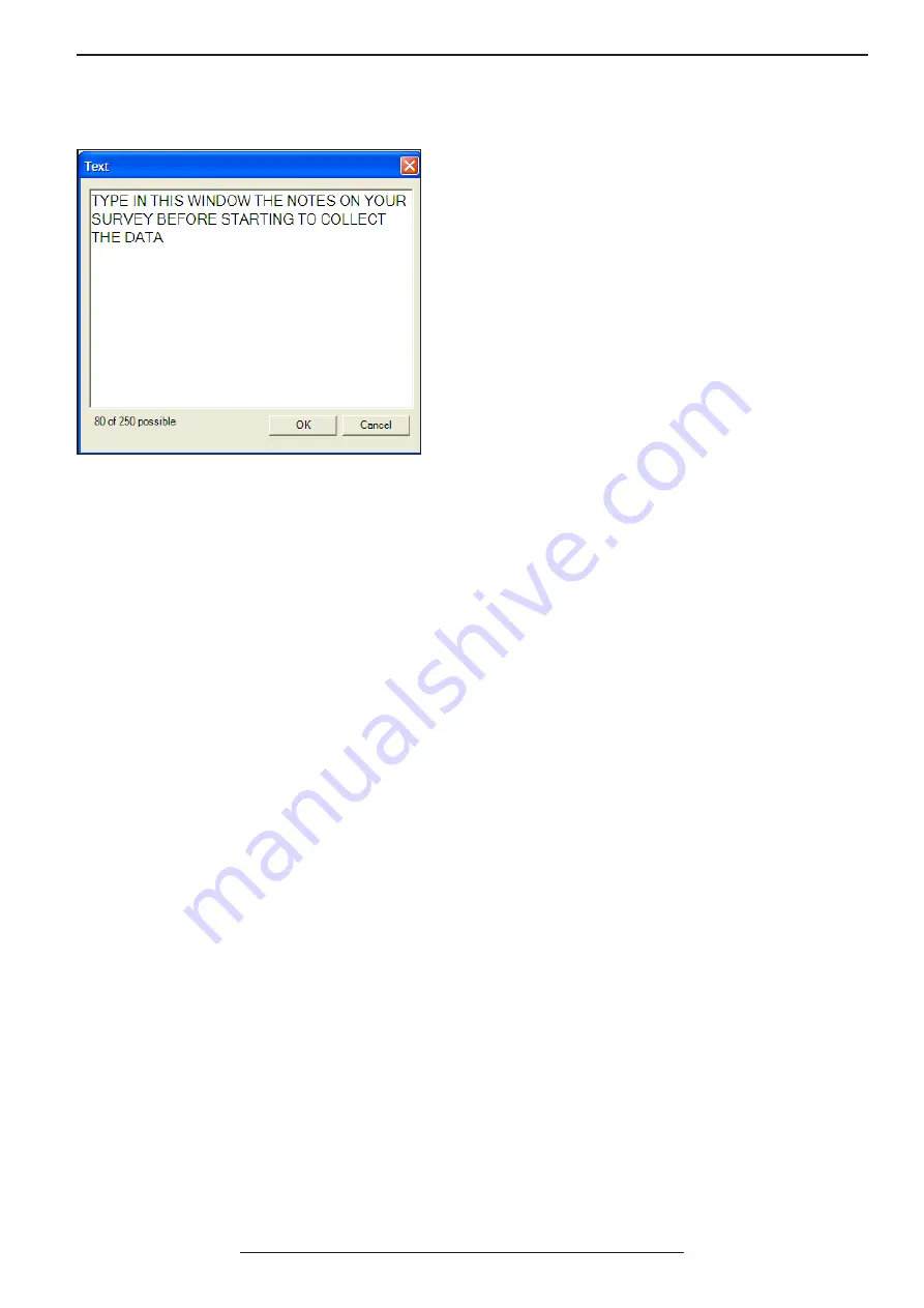
particular file. GAS™ has an easy way of adding notes 

to your profiles so later on you can remember all these 

things that at the survey time seemed so obvious, but 

later are hard to figure out.

Press the text insert button to invoke the text dialogue 

box. In this window you can type up to a message 

with 250 characters. The characters are saved in UTF-8 

format so non ASCII characters are also supporte

When time mode is selected as the acquisition mode in the “ScanRate” section of the “Scan” box the unit will 

acquire traces within time intervals based on the amount of traces per second you have entered in the “trace/sec” 

field. In other words, the unit will acquire the specified amount of traces using an internal timer to select when to 

trigger them. This mode is particularly useful when no survey wheel is available like when surveying snow from 

a helicopter, or surveying railway ballast on a high speed train. The location information can always be retrieved 

from the GPS coordinates and normalized later on in GPRSoft PRO to obtain reliable distance information.

Adjusting the amount of traces per second gives the opportunity to increase or decrease the amount of data to 

be collected. In some cases like when doing road surveys large amount of data is very useful to be able to stack 

traces later on and reduce the amount of fluctuations due to vibrations in the antenna. While there are other 

occasions when a low amount of traces per second is desirable like for instance when running a survey on an area 

that is physically small, but doesn’t allow the use of survey wheels. This setting is very dependent on the type of 

survey you are doing and therefore a general rule is not available and a bit of experimentation is always required.

To start recording data in time mode the only thing you need to do is to press the start record button or to press 

Ctrl+R on your keyboard. The data will start coming and filling up the b-scan area showing you the collected 

data. This will happen with the update rate you selected in the “scan rate” section of the “scan box” settings. To 

stop recording the data press the stop record button or press Ctrl+S on your keyboard. When the data collection 

stops GAS™  will ask if you want to save the collected data provide that the automatic saving option in the general 

settings is unchecked. If you press “yes” then the data is saved in the path specified in the general settings 

dialogue box. 

It is important to note that GAS™  NEVER looses a data file, even if the program experience a total crash or the 

control unit stops functioning altogether. The file is constantly saved in the specified location and with the name 

indicated in the status bar while collecting the data. This happens independently on the automatic saving check 

box being selected or not. This feature is very unique to our control software and it protects many hours of work if 

operating systems errors threaten to ruin the day.

4.3

 Recording Data in Time Mode

Summary of Contents for AKULA 9000B

Page 1: ...on the latest information at the time of publication Geoscanners AB reserves the right to make changes at any time without notice to color specifications accessories materials and models For more information contact the Geoscanners AB Sales Department 46 0 92153020 2015 Geoscanners AB Sweden ...

Page 2: ...device may not cause harmful interference 2 This device must accept any interference received including interference that might cause undesired operation This device may still cause interference with radio or television reception when placed near such an appliance Do not make any changes or modifications to the equipment unless otherwise specified in the manual If such changes or modifications sho...

Page 3: ...trol cable connector is identical to the one used by GSSI Inc USA and IDS Italy the unit will not work properly with antennas from those manufacturers without the proper compatibility module Attempting to connect it to those antennas may damage your unit permanently Antennas with extra power like the unshielded VHF antennas equipped with high power transmitters require a special module to guarante...

Page 4: ...ht 2006 2015 Geoscanners AB 4 Akula 9000B control unit Control cable 3 or 6 meters long depending on package USB cable Led Acid Battery in its own pouch 7 5A h Led Acid Battery charger Generic Netbook with GAS control software and GPRSoft standard edition installed Geoscanners AB software solutions disk contains GAS and GPRSoft distribution packages Suitcase for the control unit Instruction Manual...

Page 5: ...3 3 6 Marker 23 3 7 GPS Function 24 3 8 Macro Functions 25 SECTION 4 Record Mode 26 4 1 Record Mode 27 4 2 Adding Notes to Profiles 28 4 3 Recording Data in Time Mode 28 4 4 Record Mode in Distance Mode 29 4 5 Record Mode in One Shot Mode 30 4 6 Hyperbola Fitting Tool 30 4 7 Depth Calibrating Tool 32 SECTION 5 Playback Mode 33 5 1 Playback Mode 34 APPENDICES 35 Appendix A Keyboard shortcuts 36 App...

Page 6: ...B This section explains a few preliminary steps and the basic operation of the Akula 9000B ground penetrating radar control unit AKULA 9000B Before You Start SECTION 1 ...

Page 7: ... firmly attached The charger is now ready to start the automatic maintenance of the connected battery The red LED lights up when the charger is charging the battery and the green LED lights up when the battery is fully charged The charging of the battery is dependent on the battery capacity and its power level For the first time charging please allow a minimum of 24 hours for the battery to get fu...

Page 8: ...to secure the connector in place If you have a survey wheel cable then connect it now to the survey wheel cable input of your control unit Please note that this survey wheel input is known to the software as the internal one This is important for calibration purposes and for surveys in distance mode It might be the case that you need to attach the survey wheel cable directly to the antenna In this...

Page 9: ... USB cable to your control unit and to the PC where the control application will be running Your Akula 9000B kit is supplied with a preconfigured PC so it will not need to install any additional drivers for the GPR control unit If you are using your own PC then installing the drivers might be required Press the power switch on your Akula 9000B control unit The power LED should flash now indicating...

Page 10: ...B This section explains the basic setup of the unit and how to start recording a file in time mode AKULA 9000B Basic Setup SECTION 2 ...

Page 11: ...ngs stored and this data is displayed for your review This mode is known as setup mode and you will come back to it every time changes to the settings are required The data acquisition can be stopped or started by pressing the button Stop Apply at the bottom of the setup panel on the right The settings loaded in GAS at the moment may or may not suit the connected antenna At this moment you can cho...

Page 12: ...Alternatively you can press Ctrl R keys on your keyboard The data should start filling up the screen and moving the antenna over some buried object will produce signatures in the data that will be analyzed later on To stop collecting the data press the button next to the start record button which is enable only while recording the data Your data is now available in the default directory See Global...

Page 13: ...B This section gives a detailed review of all the setup functions of the control software and how they affect the collection of the data AKULA 9000B Full Unit Setup SECTION 3 ...

Page 14: ...need to return to the setup mode operation of the unit The same can be done by pressing Ctrl E on your keyboard 2 Record Mode Icon this button is available in all modes as well click on it when the setup of the unit has been completed and you need to start collecting data You can also activate the record mode by pressing Ctrl D on your keyboard 3 Play back Mode Icon this button is also available i...

Page 15: ...nd of survey you are performing 13 This is the filters tab for opening the filters box In the filters box you have all the settings for applying filters to the acquired data 14 The wheel calibration tab opens the wheel calibration box where the selection and calibration of the survey wheel can be done 15 Press this button every time you need to apply the changes made in the setup and send this inf...

Page 16: ... and the screen shots images that GAS can produce If the save automatically check box is checked then all files are saved and an increasing number is assigned to each next collected profile The files are always stored in the default directory for the data files gsf files If this check box is not checked then every time one presses stop during collection mode a dialogue window asking to save or dis...

Page 17: ...tting NMEA 0183 format only Please consult with the manufacturer of your GPS receiver if this option is available and how to activate it The other important moment to think about is that the control software will only establish communications with GPS outputting data via serial ports real or virtual ones The vast majority of the GPS receivers currently on the market uses this kind of communication...

Page 18: ...change the settings for all the filters implemented in GAS Finally the Wheel Calibration button has all the required controls for calibrating and selecting the survey wheel It is important to note that as soon as you start changing settings in the setup panel the data acquisition is stopped immediately This however doesn t mean that the new settings have been transferred to the control unit and ap...

Page 19: ...alibration of the survey wheel to guarantee that the unit will collect the proper amount of traces One Shot Mode In this mode the radar will collect one trace every time the one shot button is pressed or press enter while in record mode GAS will send the command of acquiring one trace only when the button has been pressed and released holding the button down won t result in the unit acquiring seve...

Page 20: ...d in decibels and can be selected within the maximum and minimum available values for your particular ground penetrating radar model It is important to notice that heavily over gained signals will never provided a good and useful data Applying gain to very long ranges will not make new data to appear but rather will distort the data that is available in the more shallow regions The effect in these...

Page 21: ...aution must be exercised when using the stack filter specially if fast changes of the target geometry are expected The subtract background check box will as expected subtract a previously collected background averaged trace from each and every collected trace in the incoming data It is obvious then that the background noise must be collected before you can use this filter First specify the amount ...

Page 22: ... down menu has a preselection of most common values 5 10 15 etc This doesn t mean that you cannot type in yourself any other value When you have selected the calibration distance put your survey wheel at the start of the calibration distance track press the button start and move your cart wheel forward until you reach the end of the track All this time the digits in the field current count should ...

Page 23: ...and click on it a blue rectangle around it indicates that the palette now is selected The transform preview will show how the palette is used for different levels of amplitude of the incoming signal In the transform box you can select the type of transform you need to use for your particular data In some cases it is necessary to enhance the weak signals and make the data blind to strong reflection...

Page 24: ... labeled Test GPS In order to get the best from your GPS receiver let it run for a while so a fix position has been established and you have the most accurate data it can provide If you have a GPS that support A GPS then check that the almanac is up to date and that the fix is correct If your GPS supports high update rate you might want to use it for fast acquisition surveys Press the GPS button l...

Page 25: ...xamine which parameters are going to be applied to your unit and whether or not they suit your particular survey The selected macro can now be deleted by pressing the Delete button or can be loaded into the setup of GAS by pressing the button Open The latest will also close the macro functions window and will return the application to the main setup window This macro however is still not loaded in...

Page 26: ...B This section covers the record mode hyperbola fitting tool and depth calibration of the unit AKULA 9000B Record Mode SECTION 4 ...

Page 27: ... the specified there directory in your PC 3 Start Record Icon Press this button to start recording data in all three modes time distance or one shot 4 Stop Record Icon Pressing this button will end the current started record session 5 One Shot Icon This button is used in one shot mode to record a single trace You need to press and release to be able to do another trace 6 One Shot Icon This button ...

Page 28: ...doing road surveys large amount of data is very useful to be able to stack traces later on and reduce the amount of fluctuations due to vibrations in the antenna While there are other occasions when a low amount of traces per second is desirable like for instance when running a survey on an area that is physically small but doesn t allow the use of survey wheels This setting is very dependent on t...

Page 29: ...s per unit of distance might be best suited for the application To start recording the data you need to press the start record button or press Ctrl R on your keyboard exactly the same as in time mode However no data will appear on the b scan area until your survey wheel starts moving forward according to the calibrated value Moving forward will continue adding traces to the b scan area until the s...

Page 30: ...e trace but it will also add a marker to it Pressing the marker button in the main toolbar will have the same effect Stop collecting the data and exit by pressing the stop record button or by pressing Ctrl S on your keyboard As with all other modes the control software will ask about saving the data if the automatic saving check box in the general settings was left unchecked 4 6 Hyperbola Fitting ...

Page 31: ...ipe buried in the ground in a basement at 40cm below the surface according to the drawings of the house The second hyperbola is a shallow metal water pipe embedded in the concrete slab of the floor The bottom of the concrete slab bottom is clearly seen in the b scan area Press the hyperbola fitting tool button to start the tool A red line showing us where the antenna is at the moment with a calcul...

Page 32: ...o buttons on the b scan area but this time only two buttons one with an arrow up and one with an arrow down A vertical red line with a short horizontal line also appears on the b scan area Move the antenna backwards until you have located the red line with the short horizontal line exactly on the target we are interested in Using the up or down buttons on the screen or the up down arrows on your k...

Page 33: ...B Playback Mode This section explain how to use the playback mode available in GAS AKULA 9000B SECTION 5 ...

Page 34: ...ted When GAS tries to connect to the radar upon start and displays the message radar not found just press cancel and then press the playback mode button to enter playback and review previously collected files Press the open file button to open the explorer dialogue window select the file you want to playback and press open Please note that if no radar has been found then the record mode button is ...

Page 35: ...BAKULA 9000B Playback Mode APPENDICES ...

Page 36: ...D Puts the unit in the record mode All Ctrl W Puts the unit in playback mode All Alt P Opens the palette dialogue box Record Ctrl R Start recording data to file Record Ctrl S Stop recording data to file Setup Record Alt M Opens the macro dialogue box Record Ctrl H Enters the hyperbola fitting tool session Record Alt D Enters the depth calibration tool session Setup Record Space Puts a marker in th...

Page 37: ...istance Point Data Storage 16 bit data in proprietary GSF format Power Supply 10 15VDC Interface USB 2 0 Survey Wheel Power Output 5 01Volts 0 2A max Power consumption 8 4Watts Operating Temperature Note 2 20 C to 50 C Humidity 96 non condensing Ingress Protection Note 3 IP54 Dimensions LxWxD 305x240x55 mm Weight Note 4 2 5kg Technical Specifications of the AKULA 9000B Note 1 Equivalent bandwidth ...

Page 38: ... 25 Freshwater 81 33 0 01 Freshwater Ice 4 150 0 1 2 Granite Dry 5 134 0 5 3 Granite Wet 7 113 2 5 Limestone Dry 7 113 0 5 10 Limestone Wet 8 106 1 20 Permafrost 4 8 150 106 0 1 5 Rock Salt Dry 4 7 150 113 0 01 1 Sand Dry 2 6 212 122 0 01 1 Sand Wet 10 30 95 55 0 5 5 Sandstone Dry 2 5 212 134 2 10 Sandstone Wet 5 10 134 95 4 20 Sea Water 81 33 100 Sea water Ice 4 8 150 106 1 30 Shale Dry 4 9 150 1...

Reviews: