Georges Renault CVIS II Operator'S Manual Download Page 51

6159932410-02

English

51 / 76

TIGHTENING STRATEGIES

5 - ANGLE +  TORQUE RATE CONTROLLED TIGHTENING

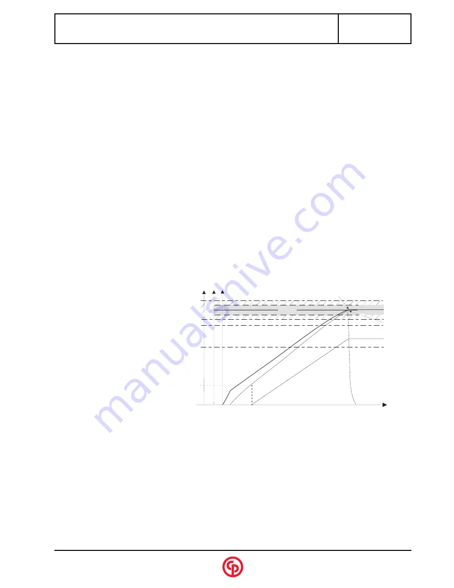
6 - STRATEGY INCLUDING ADDITIONAL CONTROL (CURRENT)

To make the fastening task even more reliable, it is possible to add a current control to most tightening strategies (torque,
angle, angle+torque, etc.).
This additional control enables you to check the coherence between the value of the torque measured by the torque transducer,
and the current consumed by the motor.
This "current" information varies from one tool to another and is not calibrated against the torque. It is thus necessary to establish
a similarity on an experimental basis for each tool: you must read the value of the maximum current reached at the end of a cycle
and then execute that cycle at least 3 times to define the "minimum current" and "maximum current" value to be programmed.

Spindle stop

IF

 angle 

 target angle 

OR

 torque > max. torque

OR

 torque rate < min. torque rate 

OR

 torque rate > max. torque rate

Accept report

IF

 min. torque < final torque < max. torque

IF

 min. angle < final angle < max. angle

IF

 min. torque rate < final torque rate < max. torque rate

according to the option selected (mean torque or min./max. torque)

Spindle stop

Stop condition for the tightening strategy
selected

OR

 current 

 max. current

Accept report

Accept report condition for the tightening
strategy selected

AND

 min. current < current < max. current

O b j e c t i v e

P e a k

t o r q u e

F i n a l   a n g l e

T i m e

A n g l e

t h r e s h o l d

A

ng

le

To

rq

ue

M a x

M i n

M a x

M i n

In

te

ns

ity

P e a k

c u r r e n t

M a x

M i n

Summary of Contents for CVIS II

Page 1: ...rights reserved Any unauthorized use or copying of the contents or part thereof is prohibited This applies in particular to trademarks model denominations part numbers and drawings Use only authorize...

Page 2: ...3 Navigation keys 10 2 4 Menu block diagram 11 SECTION 3 INITIAL START UP 1 ON RECEIVING THE CONTROLLER 13 2 INSTALLATION 13 2 1 Mains connection 13 2 2 Instant stop wiring 13 2 3 Power consumption 13...

Page 3: ...ng the differential circuit breaker 31 2 5 Autotest cycle 32 3 TROUBLE SHOOTING HELP 33 3 1 Warning 33 3 2 Coded messages 33 3 3 Messages in plain text 33 3 4 Operating problems due to adjustment prob...

Page 4: ...6 TABLE OF CONTENTS APPENDIX 2 PRINTING FORMATS FOR RESULTS 55 APPENDIX 3 CYCLE FLOWCHART AND TIMING CHART 63 APPENDIX 4 CABLES AND CONNECTORS 67 APPENDIX 5 ELECTRONIC BOARDS 71 APPENDIX 6 PARTS LIST...

Page 5: ...path to carry electricity away from user Never replace the fuses by fuses of higher value Never replace fuses by a short circuit Avoid body contact with grounded surfaces such as pipes radiators range...

Page 6: ...10 A curve D Single phased 115V 20A curve D 5 TOOL USE HAZARDS There is a real burning risk when in contact with the accessible parts of the tool The selection of the tool and of the controller takes...

Page 7: ...inside of the controller shall not be serviced until at least one minute has elapsed after switching off the controller It is necessary to check that the capacitors are completely discharged Since th...

Page 8: ...6159932410 02 English 8 76 SAFETY INSTRUCTIONS...

Page 9: ...e Torque Angle Angle Torque Optional current monitoring 1 2 Number of cycles and phases The system allows you to perform 15 tightening cycles of 8 phases each The cycles are numbered from 1 to 15 4 qu...

Page 10: ...s Y no entry unauthorised entry tool not connected or in operation X cycle in progress on the top left hand side of the screen X reject report OK accept report decimal point the decimal point format i...

Page 11: ...SPLAY RESET PRINTING SPINDLE PERIPHERALS CHANNEL TEST COUNTERS TEST CYCLE STATION CONTRAST DATE LANGUAGE ACCESS CODE PARAMETERS MAINTENANCE SERVICE Second level menus SPINDLE RUN AMPLIFIER TEST INPUTS...

Page 12: ...6159932410 02 English 12 76 DESCRIPTION AND OPERATION...

Page 13: ...onsumption per channel depends on the type of tool which is connected on the type of joint and on the tightening frequency However due to the heat dissipation of the servodrives the maximum average po...

Page 14: ...yed Use the T and S keys to select the language used by the controller and press O to validate Specify whether this screen should be displayed next time the controller is switched via start up selecti...

Page 15: ...der and the footer are not printed format PC2 PC3 PC4 specific PC5A PC5B PC5C typeall reject accept Press W to validate Press O or L to display the Main menu 13 57 Nm 34 3 4 DF 4 Accept 1 Airbag Next...

Page 16: ...he cause of the problem For further information refer to the Maintenance section 3 3 Initial start up flowchart Start Connect the tool Switch on the controller Does the screen light up Check the prese...

Page 17: ...d V to change the number and use the S and keys to move through the field Press O to validate or L to exit the screen without saving changes 3 4 4 Access Code With the access code the user can protect...

Page 18: ...6159932410 02 English 18 76 INITIAL START UP...

Page 19: ...f the Spindle valida tion on Run reverse parameter is selected Selecting none which is the default value prohibits this function Error acknowledgement yes no When this function is programmed on yes th...

Page 20: ...ly per cycle 230V 120V 230V by default indicates mains voltage to the controller This parameter is used in the ergo stop function Submenu INPUTS or OUTPUTS The various input output functions can be al...

Page 21: ...lidate The list of the cycles is displayed Select the cycle using the U and V keys and press W to validate Comment allows you to customise the cycle 14 characters as a maximum Number of cycles OK 1 99...

Page 22: ...tening acceleration rate 0 02 s more flexible transition To be used on standard or soft tightening 0 04 s as a minimum is recommended Power 0 100 Torque reset yes no Angle reset yes no The reset funct...

Page 23: ...se When a report is rejected max torque or angle reached etc it is possible to apply a specific corrective action to the cycle either by stopping the cycle or by programming a corrective phase Example...

Page 24: ...tarting the phase Prevailing offset ignore add to the measurement subtract from the measurement The average value of the prevailing torque is used as an offset to be added to or subtracted from the re...

Page 25: ...ted from the main program to one of these phases refer to jump and action on NOK phases 3 10 Changing the Programming of a Cycle flowchart Validate W Select cycle number U V Validate W If the correcti...

Page 26: ...000 Operator s Manual Press O to save the parameters 4 3 Report output format PC2 PC3 PC4 Specific PC5A PC5B PC5C on request at end of cycle the tightening results are transmitted on the serial link e...

Page 27: ...ppress the data To delete the results of a station press S T enter yes or no to confirm and press W to validate 3 PRINTING A screen allows you to set the printing parameters Peripheral printer compute...

Page 28: ...6159932410 02 English 28 76 RESULTS...

Page 29: ...ge of 10 V and an amplifier gain of 200 Torque Unbalance Test The purpose of this test is to monitor the drift of the torque transducer and amplifier line gain versus time It is automatically started...

Page 30: ...er of cycles run by the tool Validate the highligthted Reset function by pressing the W key to reset the partial counter of the tool 2 OTHER MAINTENANCE OPERATIONS 2 1 Resetting the controller It may...

Page 31: ...ing the differential circuit breaker The test procedure is as follows switch off the controller open the door with the triangular wrench switch on the controller run the tool press the test button on...

Page 32: ...he following flowchart the accept report or reject report information gives the result The following parameters are for information only Max time 1 s Tightening type torque and angle Tmin 0 Nm Ttarget...

Page 33: ...en set to on No spindle validation signal although the corresponding parameter in the Station Menu is activated No spindle programmed in the cycle E06 Station ready signal fault for instance for MULTI...

Page 34: ...er higher than maximum filter The statistical calculation parameters are incorrect Minimum filter higher than minimum tolerance The statistical calculation parameters are incorrect Minimum tolerance h...

Page 35: ...01 02 06 07 08 Tmin The torque reached at the end of the cycle is lower than the program med minimum torque 04 05 09 10 19 20 21 22 23 24 25 26 27 28 Tool change The serial number of the connected too...

Page 36: ...The tool is not suited to the task 05 Check that the tool performances are compati ble with the required torque Dispersion or abnormal deviation in the tightening results The rundown torque is too hig...

Page 37: ...stop button is not engaged MESSAGE Tool fault tool link error The electrical links between the controller and the tool are faulty 14 The cable s is are not connected The connectors are insufficiently...

Page 38: ...the operator releases the trigger before the end of the time delay Interruption of at least 2 phases of the motor Resolver fault or resolver link fault this incident can be detec ted in different ways...

Page 39: ...n that case it will be necessary to program the tool memory again This operation can only be performed in superu ser mode by authorized operators access code One of the three phases is not activated T...

Page 40: ...ly the tool LEDs should blink The motor stops suddenly per forming another action on the trigger starts the tool again The serial link between the tool and the controller is disrupted This could be du...

Page 41: ...ndices at the end of this document 2 CONNECTIONS AND PERIPHERALS 2 1 Connection side view Servodrive board Microprocessor Board mains supply Inputs Outputs Fuse box On Off switch PC serial port SubD 9...

Page 42: ...51 20J Former compatible range EML60 20J ER20J ER20DJ ERP20J EML60 30J ER30J ER30DJ ERP30J EML80 40J ER50J ER50DJ ER90J ER70DJ ER120J ER180J cycle number Binary coding 1 2 4 8 The cycles are numbered...

Page 43: ...0 at the end of the cycle number of cycles OK This signal switches to 1 when the number of cycles run with an Accept report is equal to the programmed number of cycles OK accept report Sent to the PLC...

Page 44: ...outputs List of available functions inputs CYC1 Cycle 1 acknowledge CYC1 Cycle 1 CYC2 Cycle 2 acknowledge CYC2 Cycle 2 CYC4 Cycle 4 acknowledge CYC4 Cycle 4 CYC8 Cycle 8 acknowledge CYC8 Cycle 8 INCYC...

Page 45: ...ing curves saving the parameters and results on floppy disk to secure the traceability of the applications transferring data to spreadsheet results and curves for subsequent analysis connecting a bar...

Page 46: ...is described in the appendix located at the end of this document Pin Signal 1 2 RXD 3 TXD 4 5 0V 6 7 RTS 8 CTS 9 Wiring diagram of the PC connector Link RS422 Pin Signal 1 R 2 R 3 T 4 5 0V 6 7 8 9 T...

Page 47: ...printers are recognised by the system The connection is provided by the 25 pt connector located on the controller side by means of a standard cable for parallel printer 2 6 Instant stop connector The...

Page 48: ...6159932410 02 English 48 76 CONNECTIONS AND INSTALLATION...

Page 49: ...must be adapted through successive approaches In most joints the bandwidth is equal to 128 Hz The start of the angle threshold counting should be within the linear area of the torque increase The angl...

Page 50: ...te The torque rate computation is based on the principle of the yield point computation Starting from the angle threshold the system measures the rotation angle of the spindle After 16 or 32 the first...

Page 51: ...maximum current reached at the end of a cycle and then execute that cycle at least 3 times to define the minimum current and maximum current value to be programmed Spindle stop IF angle target angle...

Page 52: ...ning unit The thermal contact located in the motor provides protection in case of overheating The max torque must be programmed to a value higher than the desired stall torque This phase allows you to...

Page 53: ...of the torque rate The system stops when the torque rate becomes lower than the reference torque rate by X X being the percentage of the target torque rate It is the yield point The default values ar...

Page 54: ...rget angle OR torque safety torque Accept report IF torque safety torque AND min torque final torque max torque AND min angle final angle max angle f i n a l a n g l e 1 0 0 2 0 0 3 0 0 4 0 0 5 0 0 6...

Page 55: ...LF instead of LF Example of result CR 0109T 00400 LF CR 0109A 01200 LF CR 0109TR 00580 LF 1 char CR 2 range or cycle number 2 fastener number 3 T 5 torque in 1 10 of Nm 1 LF 1 1 CR 2 range or cycle n...

Page 56: ...rt code see chart below 6 date year month day 6 time hour minute second 8 torque 5 Angle 1 CR 1 Checksum modulo sum 256 of the previous characters not calculated for the moment 1 LF Report code ASCII...

Page 57: ...e used for digital report outputs or printouts All these codes correspond to specific displays The table below shows the corresponding codes displayed On the contrary if some messages on the screen do...

Page 58: ...ORMATS FOR RESULTS Code emitted on 3 letters Code displayed on the screen 1st Letter 2nd Letter 3rd Letter A Accept R R t Tmin T TMAX a Amin A AMAX r Rmin R RMAX m Mmin M MMAX G Grou V Srv P Prg S Esc...

Page 59: ...f low report 05 11 if accept report xx 10 if high report 06 00 on servodrive fault xx spindle belonging to reject group 07 cycle start drop xx cycle not completed for spindle 08 transducer fault e g i...

Page 60: ...otation 04 TR torque rate report xx where TR AA or TT 01 if low report 05 11 if accept report xx 10 if high report 06 00 on servodrive fault xx spindle belonging to reject group 07 cycle start drop xx...

Page 61: ...0 0 Nm 30 31 31 30 30 xx xx xx xx xx minimum angle in 1 10th of degree ASCII notation e g 100 0 30 31 30 30 30 xx xx xx xx xx target angle in 1 10th of degree ASCII notation e g 105 0 30 31 30 35 30 x...

Page 62: ...e in 1 100th of Nm degree ASCII notation e g 1 30 Nm 30 30 31 33 30 xx xx xx xx Results of spindle 1 x times the number of spindles 01 spindle number xx applied torque ASCII notation e g 100 1 Nm 30 3...

Page 63: ...k n o o p t i o n a l S p i n d l e v a l i d a t i o n 1 i f n e c e s s a r y S t a r t c y c l e 1 c y c l e e n d i n c y c l e 0 s t a r t c y c l e 0 R e a d O K N O K r e s u l t s E n d S t a...

Page 64: ...rt which is sent to the PLC phase 5 the in cycle signal returns to zero when all the operations of the system are over To optimise cycle time the PLC or digital control can be synchronised with the ac...

Page 65: ...NG CHART Timing chart when using a crowfoot tool Start cycle Cycle in progress Screwdriver status Report Reset Nutrunner LEDS Dispay result Controller LEDS NCYOK Tightening n Indexing n B M Blinking B...

Page 66: ...6159932410 02 English 66 76 CYCLE FLOWCHART AND TIMING CHART...

Page 67: ...act blue ON OFF white ACCEPT REPORT white grey REJECT REPORT black COS white COS yellow EXEC red EXEC black SIN blue SIN green 25 point Female insert P N 6159152940 A B C D 5 1 16 2 12 6 7 17 8 9 18 1...

Page 68: ...OFF white ACCEPT REPORT orange REJECT REPORT light green COS white COS yellow EXEC red EXEC black SIN blue SIN green 25 point female extension cable A B C D 5 1 16 2 12 6 7 17 8 9 18 19 20 21 4 A B C...

Page 69: ...ite grey 15V red 15V white CAL yellow white yellow MISO green white green CS MON brown white brown AGND black 1 2 3 4 5 6 7 8 9 10 1 2 3 4 5 6 7 8 9 10 Lot Ref XXX XXX C EXC purple EXC green SIN yello...

Page 70: ...A F T E R A N G L E A D J U S T M E N T D E P E N D S O N U S E 6 1 5 9 3 0 6 1 9 0 6 1 5 9 3 0 6 2 0 0 Connector SubD 9 point contact socket PC side Connector SubD 9 point contact socket controller...

Page 71: ...RVODRIVE BOARD 8515 2 1 Features 2 2 Function Controls autosynchronous 6 pole motors equipped with a resolver type location sensor 2 3 Description 6U board integrated in a shielded 12TE drawer and fit...

Page 72: ...RDS Overall size 261 75 x 60 62 x 250 mm Description of the front side of the servodrive board TEST VP 18V 5V OK differential test power voltage voltage 18 Volts voltage 5 Volts differential error ser...

Page 73: ...188270 Microprocessor power supply I O board 8606 6159189980 CVIS II keyboard 8279 6159234610 Display 8602 1502 6159188130 Display board 8602 6159224770 Chemical condenser 5600 F 400V 2050478153 Warni...

Page 74: ...6159932410 02 English 74 76 PARTS LIST...

Page 75: ...o a higher extent eliminates more interferences but it is slower which may result in a difference between the torque applied and the torque measured by the system Cycle A cycle is a tightening program...

Page 76: ...fault Safety torque This is a torque value which causes the tool to stop when the said value is reached whereas all the other stop conditions have failed This applies to the strategies where the stop...

Reviews: