background image

BLIZZARD 400-800 C ENC 

29 

532104 - Rev.A

 4 7

Tr

ansla

tion of the orig

inal instruc

tions

ENGLISH

9.1   RQFZ RADIO MODULE

L

i

The SPRINT M24 electronic board is fitted with an integrated two-

channel decoding system. The RQFZ module makes it possible to 

memorise  GENIUS RC and JLC radio controls: the two types of radio 

codes can coexist simultaneously.  A maximum of 256 codes can be 

memorised.  Make sure that the radio controls and the RQFZ module 

have the same transmission frequency.
The first channel (

RADIO1

) commands a total opening, whilst the second 

channel (

RADIO2

) commands a partial opening.

The gate cannot be closed using the radio control.
When memorising the codes, keep the radio control approximately one 

metre from the RQFZ module.

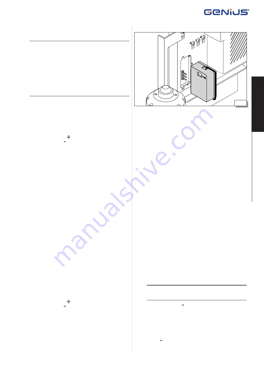
1.  Switch off power to the system.
2.  Plug in the RQFZ radio module into connector J7, taking care to 

insert it in the right way round (

 4 7

).

3.  Memorise the radio controls.

MEMORISING JLC


RADIO CONTROL CODES

First radio control:

1.  Press and hold down the 

+

 button on the electronic board to 

program 

RADIO1

 or the 

-

 button to program 

RADIO2

. After ap-

proximately 5 s, the LED corresponding to (

RADIO1

 or 

RADIO2

starts to flash slowly for approximately 20 s. Release the button.

2.  Press and hold down buttons P1 and P2 simultaneously on the JLC 

radio control. The LED of the radio control starts to flash. Release 

both buttons.

3.  While the LED of 

RADIO1

 or 

RADIO2

 and the LED of the radio 

control are flashing, press and hold down the required button 

on the radio control. The LED of the radio control turns on with 

a steady light.

4.  The 

RADIO1

 or 

RADIO2

 LED turns on with a steady light for 1 s and 

then turns off, indicating that it has been memorised. Release the 

button of the radio control.

5.  Press the button twice in succession on the radio control that 

was memorised to complete the memorisation procedure. The 

automation will open the gate.

Other radio controls:

1.  Press and hold down buttons P1 and P2 simultaneously on the 

radio control that has already been memorised. The LED of the 

radio control will start to flash. Release both buttons.

2.  While the LED of the radio control is flashing, press and hold down 

the button that has already been memorised. The LED of the radio 

control turns on with a steady light.

3.  Bring the radio control to be memorised up to the one that has 

already been memorised. Press and hold down the button of the 

radio control to be memorised. The LED of the radio control to be 

memorised flashes twice, indicating that it has been memorised.

4.  Press the button twice in succession on the radio control that 

was memorised to complete the memorisation procedure. The 

automation will open the gate.

MEMORISING RC


RADIO CONTROL CODES

1.  Press and hold down the 

+

 button on the electronic board to 

program 

RADIO1

 or the 

-

 button to program 

RADIO2

. After ap-

proximately 5 s, the LED corresponding to (

RADIO1

 or 

RADIO2

starts to flash slowly for approximately 20 s. Release the button.

2.  While the 

RADIO1

 or 

RADIO2

 LED is flashing, press the required 

button on the RC radio control.

3.  The 

RADIO1

 or 

RADIO2

 LED turns on with a steady light for 1 s 

and then turns off, indicating that it has been memorised. It sub-

sequently starts to flash again for a further 20 s, during which it is 

possible to memorise another radio control.

9.  ACCESSORIES

MEMORISING RC


RADIO CONTROL CODES REMOTELY

Additional RC radio controls can be memorised remotely, without 

having to use the board directly, by using a radio control that has 

already been memorised.
1.  Bring a radio control that has already been memorised close to 

the board.

2.  Press and hold down buttons P1 and P2 simultaneously on the 

radio control. The LED on the radio control starts to flash. Release 

both buttons.

3.  Press the previously memorised button of the radio control within 

5 s to activate the learning phase on the relative channel (

RADIO1


or 

RADIO2

).

4.  The 

RADIO1

 or 

RADIO2

 LED flashes for 20 s within which you have 

to press the required button on the other radio control

5.  The 

RADIO1

 or 

RADIO2

 LED turns on with a steady light for 1 s 

and then turns off, indicating that it has been memorised. It sub-

sequently starts to flash again for a further 20 s, during which it is 

possible to memorise another radio control.

DELETING RADIO CONTROL CODES


!

This procedure cannot be reversed and deletes all the radio control codes 

memorised on both channels. The deletion procedure is only enabled 

in the gate status display mode.

1.  Press and hold down the 

-

 button.


-

After pressing the button for approximately 5 s, the 

RADIO2

 LED 

starts to flash slowly. After another 5 seconds of slow flashing 

and keeping the button pressed, the 

RADIO1

 and 

RADIO2

 LEDS 

start to flash more quickly.


-

When the fast flashing stops, the 

RADIO1

 and 

RADIO2

 LEDS turn 

on steadily to confirm that all the radio codes have been deleted.

2.  Release the 

-

 button.

Summary of Contents for BLIZZARD 400 C ENC

Page 1: ...BLIZZARD 400 C ENC BLIZZARD 800 C ENC...

Page 2: ...ts reserved No part of this manual may be reproduced archived distributed to third parties nor copiedinanyotherway inanyformatandwithanymeans beitelectronic mechanical or by photocopying without prior...

Page 3: ...ration 14 5 6 Installing the Rack 15 5 7 Adjustments and checks 17 6 SPRINT M24 BOARD 18 6 1 Connections 19 7 START UP 22 7 1 Power supply and earthing 22 7 2 LEDs check 22 7 3 Installation of the lim...

Page 4: ...tion Gearmotors for sliding gates Model BLIZZARD 400 C ENC BLIZZARD 800 C ENC The essential requirements of the Machinery Directive 2006 42 EC including all applicable amendments that have been applie...

Page 5: ...uired by law among other things to carry out a risk analysis of the machine automatic gate in its entirety and take protective measures to fulfil the essential safety requirements specified in Annex I...

Page 6: ...contained in the instructions and warning tables at the beginning of the paragraphs Always comply with the safety recommendations Only the installer and or maintenance technician is authorised to wor...

Page 7: ...an those specified or use them for purposes not intended and authorised by their respective manufacturers Do not allow water jets of any type or size to come into direct contact with the gear motor Do...

Page 8: ...e if there is a mains power supply failure L L Revision 1 battery kits are not compatible the revision number must be 1A or higher Check the revision number on the label of the battery kit board 3 4 E...

Page 9: ...tor with integrated encoder 4 Electronic board SPRINT M24 5 Magnetic limit switches 6 Release device 7 Battery kit compartment 8 Earth connection 9 Power cable clamps 10 Z16 module 4 pinion 7 Installa...

Page 10: ...eights mustbesolidandtheremustbenoriskofdetachment or collapse considering the weight of the leaf and the forces applied by the gearmotor and wind action Perform structural calculations where necessar...

Page 11: ...ILL BIT of specified sizes M8 THREAD CUTTER of specified sizes for steel rack to be screwed on LEVEL 1 Mains power supply 3 x 1 5mm2 2 Circuit breaker 3 Junction box 4 Blizzard gearmotor 5 Bus G WayTX...

Page 12: ...8 90 0 50 50 7 90 0 50 95 288 132 50 6 288 132 Translation of the original instructions ENGLISH POSITIONING THE NYLON RACK Foundation Nylon rack 5 2 INSTALLATION DIMENSIONS POSITIONING THE FOUNDATION...

Page 13: ...The foundation plate and corresponding hardware are accessories which are not included 1 Assemblethefoundationplateasshownin 11 tightentheM10 nuts and lock nuts supplied using two hex spanners 2 Make...

Page 14: ...port nuts 14 1 5 Fit four M10 lock nuts and four washers supplied together with the foundation plate as shown in 14 2 6 Makesurethereisadistanceof13 5mmbetweenthepinionandtheleaf 5 2 7 Useaspiritlevel...

Page 15: ...ents if the guide were to move downwards 16 1 if an element of the rack needs to be shortened cut it using an angle grinder away from the slot 19 2 Open the leaf manually 3 Rest an element of the rack...

Page 16: ...inion Repeat steps 3 5 for the other fixing points 7 Move the leaf Rest the next element of the rack on the pinion so that it is touching the previous element Line up the teeth by resting them on an e...

Page 17: ...n angle grinder away from the slot 25 5 7 ADJUSTMENTS AND CHECKS RISKS PERSONAL PROTECTIVE EQUIPMENT L L The operations described in this section are fundamentally important to the integrity and opera...

Page 18: ...utputW L J17 Connector for encoder J18 Terminal board for motor IC14 Limit switch sensor F1 Mains power supply fuse KEY DL1 Signalling LED Bus G Way device active BUS DL2 Diagnostic LED Bus G Way BUS...

Page 19: ...ntact if active commands the closing of the gate L L If logic b or C are used the input OPEN B must be configured as CLOSE in Advanced programming Ob 02 3 STOP N C stop contact Can be configured in Ad...

Page 20: ...lls and safety edges to be installed Connect the Bus devices in parallel to terminal J4 of the SPRINT M24 board 38 The Bus photocells and safety edges connection has no polarity L L The maximum permit...

Page 21: ...configured as SAFE in Advanced Programming Ob SP L L It is possible to modify the way the reverse on obstacle function works in Advanced Programming IP A Fail Safe test can be carried out on N C cont...

Page 22: ...power supply PE Earth do not remove the wire N Neutral L Phase 4 Secure the mains power cable using the appropriate clamp 42 1 5 Secure the other cables in the appropriate clamp 42 2 6 Switch on power...

Page 23: ...two washers supplied 44 2 10 Manually move the gate to its open position and check that the FCA opening limit switch LED turns off Otherwise adjust the position of the limit switch using the slots 7...

Page 24: ...stable from 00 to 59 sec in 1 second steps If 59 is exceeded the display changes to indicate minutes and tens of seconds separated by a dot with adjustment in steps of 10 seconds up to a maximum of 9...

Page 25: ...andopeninpause flashing during closing off when gate closed 01 Courtesy light active for the opening movement and for a further 90 s 00 O1 OUTPUT OUT 00 Always active 01 Fail Safe test on SAFE input 0...

Page 26: ...Logic AP requires only one command OPENwhenthegateisclosed causesittoopen Afterthepause time the gate closes automatically OPEN when the gate is open in pause stops the gate in the open state automat...

Page 27: ...ited Bus line error 3 Check the status of the Bus LEDs according to the following table STATUS MEANING DL1 BUS At least one Bus device is engaged active DL1 BUS No Bus device is engaged active DL2 BUS...

Page 28: ...tch engaged S3 Gate opening movement S4 Opening limit switch engaged 01 Setup procedure completed Gate open 8 FINAL OPERATIONS RISKS PERSONAL PROTECTIVE EQUIPMENT 1 Make sure that the forces generated...

Page 29: ...already been memorised Press and hold down the button of the radio control to be memorised The LED of the radio control to be memorised flashes twice indicating that it has been memorised 4 Press the...

Page 30: ...the electronic board 4 Switch on power to the system 10 MASTER SLAVE If installing systems that have two opposite opening leaves two BLIZZARD 400 800 C ENC must be installed The first referred to as...

Page 31: ...ided for are respected 12 Check that the manual release operates correctly when the release mechanism is activated it must only be possible to move the gate manually 6 Check that the caps on the locks...

Page 32: ...persons animals or objects Do not allow children to approach or play in the area of operation of the automation system Do not try to prevent the movement of the automation system Do not climb on hold...

Page 33: ......

Page 34: ...Sede legale FAAC S p A Soc Unipersonale Via Calari 10 40069 Zola Predosa BOLOGNA ITALY Tel 39 051 61724 Fax 39 051 758518 www geniusg com BLIZZARD 400 800 C ENC 34 532104 Rev A...

Reviews: