background image

Attaching the Mirrored Viewing Tip

The only accessory included with the P16181HP is a 110° mirrored viewing tip. To
attach it to the probe:

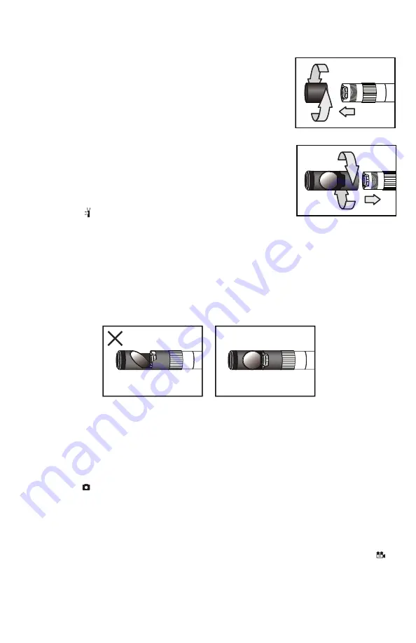
1. Pull off the rubber protective cap (Fig. 2, Callout 5).

2. Unscrew and remove the black metal thread protector

ring (Callout 4), as shown below.

3. Turn the stainless steel accessory alignment ring 

(Callout 3) clockwise to move it away from the probe tip.
Keep turning until the ring can travel no further.

4. Screw the mirrored viewing tip onto the camera head

(Callout 2) by turning it clockwise, as shown at right. 
Keep turning until the viewing tip is as far from the probe
tip as possible. In this position, it can rotate freely.

5. Press the

button to activate the two-side facing LEDs.

6. Slowly turn the mirrored viewing tip counterclockwise to move it toward the probe

tip. Once the threads of the tip grip the camera head, continue turning only until the
two LEDs are clearly visible through the gap in the tip’s housing.

7. Secure the tip with your thumb and forefinger and use your other hand to turn the

alignment ring clockwise. Keep turning the ring until its leading edge contacts the
mirrored viewing tip, locking it in place. The pair of figures below illustrate the
incorrect (left) and correct (right) orientation of the mirror with respect to the LEDs.

8. Remove the blue circular protective film from the mirror by pulling on its tab with a

tweezers.

TAKING PICTURES AND RECORDING VIDEOS

To take a picture

, make sure the DCS1700 is in Preview mode (with live video

appearing on the LCD), optimize the display brightness and zoom level for the target,
and press the

button. Doing so creates a .jpg file of the frame being displayed at that

moment and stores it on the SD card. The alphanumeric name of the stored picture file,
which begins with “PICT” and has the suffix “.JPG”, is briefly displayed in red at the
bottom of the LCD to confirm that a picture was taken. The DCS1700 automatically
returns to Preview mode after taking a picture.

T

o record a video clip

, make sure the DCS1700 is in Preview mode and press the

button. Doing so begins creating an .avi video file (with MPEG-4 compression) for
storage on the SD card. A red running clock indicating the duration of the clip recorded
so far will appear at the lower left of the screen and remain there until the recording is
stopped.

User Guide

User Guide

14

Summary of Contents for DCS1700

Page 1: ...HIGH PERFORMANCE VGA RECORDING VIDEO BORESCOPE SYSTEM USER S MANUAL DCS1700 Please read this manual carefully and thoroughly before using this product...

Page 2: ...ce Troubleshooting Tips 22 23 Compatible Probes and Accessories 24 Warranty Information 25 Return for Repair Policy 25 INTRODUCTION Thank you for purchasing General Tools Instruments General s DCS1700...

Page 3: ...os also can be viewed on a PC 1 by removing the SD card and plugging it in directly 2 through a card reader or 3 via the included USB cable Photos are saved as jpg files so most photo viewer applicati...

Page 4: ...rget clarity and detail Slow motion and fast forward video playback Brightness and contrast control video mirror and 2X video zoom buttons on grip Black white mode Object measurement mode 4GB SD memor...

Page 5: ...USB cable with a mini USB plug on one end and a full size USB plug on the other end Four AA Alkaline batteries A soft cloth a bottle of liquid and cotton swabs for cleaning the camera s lens and LEDs...

Page 6: ...esumes playback Pressed once enlarges target 50 zooms 1 5X Pressed twice enlarges target 100 zooms 2 0X Pressed three times returns to 1X viewing Moves up one line within menu or submenu In Settings s...

Page 7: ...mode Takes a picture stores jpg photo on SD card Powers console on and off Powers console on and off Powers console on and off Pressed once starts recording an avi video clip on SD card Pressed again...

Page 8: ...y marks on the inside of the cover as an orientation guide left figure at right 4 Flip down the cover and secure it by turning the screw handle clockwise right figure above Flip down the chrome screw...

Page 9: ...INTERVAL By default the Auto Power Off function of the DCS1700 is disabled To minimize how often you must change or recharge the instrument s batteries General strongly recommends that you reset the...

Page 10: ...s and system resets To increase the brightness of the display press the button To decrease brightness press the button In a brightly lit room changing the intensity of the LEDs at the tip of a probe h...

Page 11: ...sign of weak batteries is a change in the appearance of the icon from a steady white to a flashing red When the batteries are critically low the flashing will stop and the icon will switch to a solid...

Page 12: ...ntaining four forward facing LEDs and two side facing LEDs 3 Stainless steel accessory alignment ring 4 Black metal thread protector ring 5 Rubber protective cap 6 Probe handle 7 Light boost button 8...

Page 13: ...of view use the button Pressing the button adds a red backlight to it just like the other two buttons on the VGA Probe handle This anti reflection feature of the P16181HP is most useful for eliminati...

Page 14: ...Keep turning the ring until its leading edge contacts the mirrored viewing tip locking it in place The pair of figures below illustrate the incorrect left and correct right orientation of the mirror w...

Page 15: ...it out of Preview mode and into Playback mode by pressing the button The DCS1700 will then recall and display either a still photo if a photo was the last recording stored or the first frame of a vide...

Page 16: ...ure At the top of the hierarchy is a folder named DCIM Details of the SD card s file structure are worth mentioning to underscore the importance of not changing any factory assigned folder names As th...

Page 17: ...isible rows highlights it and makes it available for selection Pressing the button saves the setting and switches the display to the next highest level of that menu or submenu Pressing the button has...

Page 18: ...efault format of Y M D year month day 1 Press the or button to increase or decrease the Y value Then press the button to advance to and highlight the M field 2 Press the or button to increase or decre...

Page 19: ...take the action and return to the SD CARD STATUS submenu FORMAT SD CARD YES Choose YES to format the card realizing that NO default doing so erases its entire contents Press the button to do so The c...

Page 20: ...u power off and on again Note Unlike the Main menu and its submenus the display controls made available through the Special Function menu must be manipulated within four seconds If you do not adjust t...

Page 21: ...or object measurement mode is activated the DCS1700 will continue to operate in that mode until you deactivate it or reboot the console To deactivate either special operating mode enter the Special Fu...

Page 22: ...hours operation OPERATING MAINTENANCE TROUBLESHOOTING TIPS The probe is flexible to make it easy for you to inspect hard to reach areas Never insert or bend it by force and never over bend any part o...

Page 23: ...s probe connector use only compatible probes Never use the probe or camera head to modify surroundings or to clear pathways or clogged areas The camera head LEDs and thread protector ring are waterpr...

Page 24: ...49 3m 9 8 ft P16181HP 1m 3 28 ft P16182HP 2m 6 6 ft P16183HP 3m 9 8 ft P1618SV 1SM P1618SV 1SR P16PIP 28mm 22m 72 ft 0 4 in 10mm 1 1 in to infinity PM003 RP1618 24 Soft Metal Articulating Probe 6mm 0...

Page 25: ...eneral authorized service center freight prepaid and insured Acceptance of the exclusive repair and replacement remedies described herein is a condition of the contract for purchase of this product In...

Page 26: ...____________________________________ ________________________________________________________________ ________________________________________________________________ _________________________________...

Page 27: ...____________________________________ ________________________________________________________________ ________________________________________________________________ _________________________________...

Page 28: ...431 6100 FAX 212 431 6499 TOLL FREE 800 697 8665 e mail sales generaltools com www generaltools com DCS1700 User s Manual Specifications subject to change without notice 2012 GENERAL TOOLS INSTRUMENTS...

Reviews: