background image

GE 

RAFT

V

OLUSON

™ P8/V

OLUSON

™P6

DIRECTION 5775469, R

EVISION

 3

DRAFT (J

ULY

 19, 2018)

 B

ASIC

 S

ERVICE

 M

ANUAL

8-98

Section 8-29 - Replacement of the AIR FILTER

Section 8-29

Replacement of the AIR FILTER

8-29-1

Manpower

One person, 1 minutes

8-29-2

Tools

None

8-29-3

Preparations

1.) Power Off/Shutdown the system as described in 

4-3-2 on page 4-4

.

8-29-4

Removal Procedure

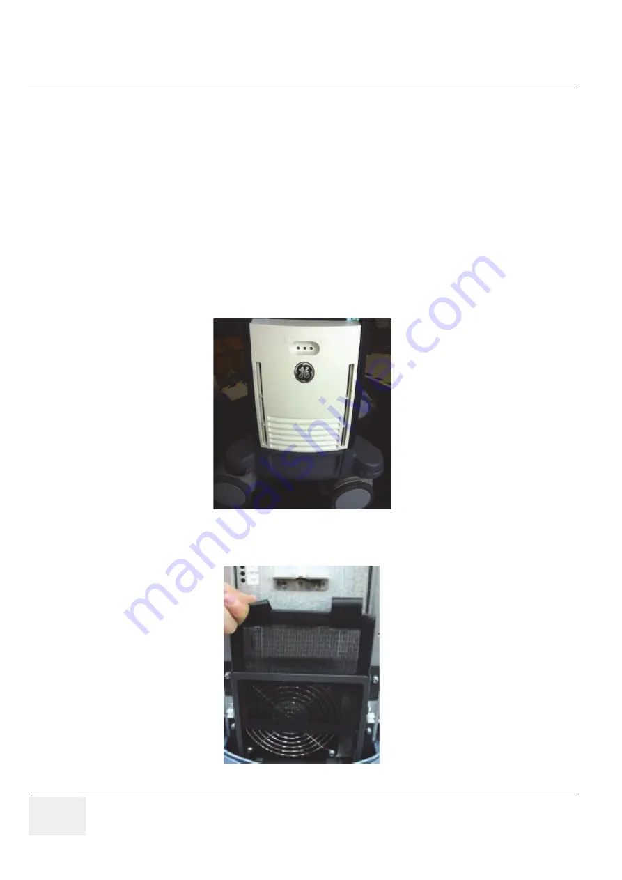
1.) Pull out the FRONT CABINET BEZEL ASSY BT16. Refer to the figure below. 

2.) Pull out the AIR FILTER. Refer to the figure below.

Figure 8-145  Removing the FRONT CABINET BEZEL ASSY BT16

Figure 8-146  Removing the AIR FILTER

Summary of Contents for Voluson P8

Page 1: ...Voluson P8 Voluson P6 Basic Service Manual Voluson P8 systems Voluson P6 systems Document Number 5775469 Revision 3 0459...

Page 2: ......

Page 3: ...ST AU CLIENT QU IL INCOMBE DE LE FAIRE TRADUIRE NE PAS TENTER D INTERVENTION SUR LES QUIPEMENTS TANT QUE LE MANUEL SERVICE N A PAS T CONSULT ET COMPRIS LE NON RESPECT DE CET AVERTISSEMENT PEUT ENTRA N...

Page 4: ...EGURAN A DO T CNICO OPERADOR OU PACIENTE DEVIDO A CHOQUES EL TRICOS MEC NICOS OU OUTROS IL PRESENTE MANUALE DI MANUTENZIONE DISPONIBILE SOLTANTO IN INGLESE SE UN ADDETTO ALLA MANUTENZIONE ESTERNO ALLA...

Page 5: ...PTAMANNS ARFNAST ANNARS TUNGUM LS EN ENSKU ER A BYRG VI SKIPTAMANNS A TVEGA INGU REYNI EKKI A J NUSTA T KI NEMA EFTIR A HAFA SKO A OG SKILI ESSA J NUSTUHANDB K EF EKKI ER FARI A ESSARI VI V RUN GETUR...

Page 6: ...RISK MEKANISK ELLER ANDEN FARE FOR TEKNIKEREN OPERAT REN ELLER PATIENTEN DEZE ONDERHOUDSHANDLEIDING IS ENKEL IN HET ENGELS VERKRIJGBAAR ALS HET ONDERHOUDSPERSONEEL EEN ANDERE TAAL VEREIST DAN IS DE KL...

Page 7: ...GER ET ANNET SPR K ER DET KUNDENS ANSVAR S RGE FOR OVERSETTELSE IKKE FORS K REPARERE UTSTYRET UTEN AT DENNE SERVICEH NDBOKEN ER LEST OG FORST TT MANGLENDE HENSYN TIL DENNE ADVARSELEN KAN F RE TIL AT S...

Page 8: ...N ENGELSKA ANSVARAR KUNDEN F R ATT TILLHANDAH LLA VERS TTNINGSTJ NSTER F RS K INTE UTF RA SERVICE P UTRUSTNINGEN OM DU INTE HAR L ST OCH F RST R DEN H R SERVICEHANDBOKEN OM DU INTE TAR H NSYN TILL DE...

Page 9: ...GE VOLUSON P8 VOLUSON P6 DIRECTION 5775469 REVISION 3 BASIC SERVICE MANUAL vii JA ZH CN KO...

Page 10: ...ical work on these products will comply with the requirements of the applicable electrical codes The purchaser of GE equipment shall only utilize qualified personnel i e GE s field engineers personnel...

Page 11: ...in any form in whole or in part without prior written permission of Voluson P8 Voluson P6 Voluson P8 Voluson P6 may revise this publication from time to time without written notice TRADEMARKS All pro...

Page 12: ...Setup Instructions pages 1 72 3 Chapter 8 Replacement Procedures pages 1 214 3 Important Precautions pages i x 3 Chapter 4 Functional Checks pages 1 68 3 Chapter 9 Renewal Parts pages 1 26 3 Table of...

Page 13: ...Icons 1 5 Safety Considerations 1 7 Introduction 1 7 Human Safety 1 7 Mechanical Safety 1 7 Electrical Safety 1 8 Safe Practices 1 8 Probes 1 8 Auxiliary Devices Safety 1 8 Labels Locations 1 10 Main...

Page 14: ...Power Plug 2 3 EMI Limitations 2 4 Probe Environmental Requirements 2 5 Time and Manpower Requirements 2 5 System Specifications 2 5 Physical Dimensions of Voluson P8 Voluson P6 2 5 Acoustic Noise Out...

Page 15: ...rinter 3 13 Connection Scheme B W Printer 3 14 Connecting the Color Printer 3 15 Connection Scheme Color Printer 3 16 Connecting the DeskJet Color Printer 3 17 Connection via Bluetooth Adapter 3 17 Co...

Page 16: ...ter Settings 3 50 UP D25MD Printer Settings 3 51 Remote Control Selection 3 53 Report Printer Selection 3 54 System Configuration 3 55 System Setup 3 55 To invoke the Setup procedure 3 56 How to enter...

Page 17: ...ting to the WLAN 3 73 Disconnecting from the WLAN 3 73 Adding a WLAN Profile 3 74 Refreshing a WLAN Network 3 74 Setting a WLAN Network as Non Preferable 3 75 Removing a WLAN Profile 3 75 Customizing...

Page 18: ...CD 4 11 Backup and Restore Database Preset Configurations and Images 4 12 Save Small Backup Scan Settings 4 13 Load Small Backup Scan Settings 4 14 Preparations 4 14 Load Complete Backup 4 15 Load onl...

Page 19: ...ISION 3 BASIC SERVICE MANUAL Table of Contents vii Low Version to High Version 4 28 Brakes and Direction Swivel Locks 4 42 Mode Transition 4 43 B Mode 4 43 M Mode 4 43 B CF Mode 4 43 PW Mode 4 43 CW O...

Page 20: ...on 5 8 3D Rendering 5 9 Block diagram Voluson P8 Voluson P6 5 10 Front End Block diagram 5 11 Back End Block diagram 5 11 OPIO Block diagram 5 11 Data Flow Control Description 5 12 B Mode 5 12 Special...

Page 21: ...Description of Hardware Options 5 22 CW Continuous Wave Doppler 5 23 ECG Module 5 23 Wireless Network Adapter WLAN Wireless Local Area Network 5 23 DPS Battery Assy 5 23 UP BT18 5 23 Data Location 5...

Page 22: ...gram 5 46 Power Up Sequence Description 5 47 Power Up Sequence Description 5 47 Power Down Sequence Description 5 48 Mechanical Concept and Overview 5 48 Functions of ACFE 5 48 ACDC primary DC Power S...

Page 23: ...5 60 Rollback 5 61 Memtest Memory Check 5 62 Windows Start Menu 5 63 LINUX Voluson Maintenance System 5 65 Overview 5 65 General Operation and Selection in LINUX and BIOS menu 5 65 Access Security 5...

Page 24: ...LUSON P6 DIRECTION 5775469 REVISION 3 BASIC SERVICE MANUAL xii Table of Contents USBTree 5 82 SmartHDDtest 5 82 HDDWipeTool 5 82 CollectLogs 5 83 CheckLnkSpeed 5 83 After Recovering or Initializing th...

Page 25: ...3 BASIC SERVICE MANUAL Table of Contents xiii CHAPTER 6 Service Adjustments Overview 6 1 Purpose of Chapter 6 6 1 Regulatory 6 1 LCD Monitor Adjustment 6 2 Modification of Keyboard Layout 6 3 Setup th...

Page 26: ...7 15 Export Log s and System Data 7 16 Export System Data by pressing the ALT D key 7 16 Export Log s and System Data via Service Page 7 18 Dump file 7 18 Remote Access to Service Platform 7 19 Genera...

Page 27: ...annels or elements 7 52 Automatic Diagnostic Test 7 53 System Overall Test 7 53 VPD 7 54 DRFG 7 54 DBM64G 7 54 DPI 7 54 DPS 7 54 DC4D 7 54 MDM 7 54 OPIO 7 54 BATTERY 7 54 DRFG Overall Test 7 55 Voltag...

Page 28: ...MI Test 7 59 Minimum Configuration to Boot Scan 7 60 Booting without using the Ultrasound Hardware 7 60 User Interface Troubleshooting 7 62 Console Test 7 62 Troubleshooting Trees Instructions and Tec...

Page 29: ...3 Overview 8 13 Update Procedure 8 13 Software and Functional Checks after Installation Upgrade Procedure 8 20 Image Settings Only Loading Procedure 8 22 Introduction 8 22 Loading Procedure 8 22 Full...

Page 30: ...8 29 Replacement of Front PEDESTAL COVER BT16 8 30 Manpower 8 30 Tools 8 30 Disassembly Procedure 8 30 Installation Procedure 8 31 Replacement of TRAY PEDESTAL CABINET PLASTIC BT16 8 32 Manpower 8 32...

Page 31: ...ic lower cover assy 8 56 Manpower 8 56 Tools 8 56 Disassembly procedure 8 56 Installation procedure 8 61 Replacement of OPIO Plastic upper cover assy 8 62 Manpower 8 62 Tools 8 62 Disassembly procedur...

Page 32: ...nt of the SPEAKER 8 91 Manpower 8 91 Tools 8 91 Preparations 8 91 Removal Procedure 8 91 Installation Procedure 8 91 Remove the PEDESTAL BOTTOM COVER BT16 8 92 Manpower 8 92 Tools 8 92 Preparations 8...

Page 33: ...er 8 103 Tools 8 103 Preparations 8 103 Removal Procedure 8 103 Installation Procedure 8 105 Replacement of the Trackball 8 106 Manpower 8 106 Tools 8 106 Removal procedure 8 106 Installation Procedur...

Page 34: ...oval Procedure 8 123 Installation Procedure 8 123 Replacement of the REAR HANDLE 8 124 Manpower 8 124 Tools 8 124 Preparations 8 124 Removal Procedure 8 124 Installation Procedure 8 126 Replacement of...

Page 35: ...DRFG 8 137 Manpower 8 137 Tools 8 137 Preparations 8 137 Removal Procedure 8 137 Installation Procedure 8 137 Replacement of the DBM64G 8 138 Manpower 8 138 Tools 8 138 Preparations 8 138 Removal Pro...

Page 36: ...N KEY TOP 8 151 Manpower 8 151 Tools 8 151 Preparations 8 151 Key Caps Removal Procedure 8 151 Replacing optional Peripherals 8 152 Manpower 8 152 Tools 8 152 Printer Installation BW and Color 8 153 B...

Page 37: ...llation Procedure 8 175 Replacement of ECG Kit assy 8 176 Manpower 8 176 Tools 8 176 Preparations 8 176 Removal Procedure 8 176 Installation Procedure 8 177 Replacement of Battery Pack Assy 8 180 Manp...

Page 38: ...rs Front Sides Rear 9 5 LCD Monitor 9 7 OPIO 9 8 Nest Box Parts 9 11 Mechanical Parts 9 13 Options 9 15 Optional Peripherals and Accessories 9 17 Printers and options 9 17 System Manuals 9 19 Probes 9...

Page 39: ...e Maintenance 10 7 System Maintenance 10 8 Preliminary Checks 10 8 Functional Checks 10 9 System Checks 10 9 Peripheral Option Checks 10 10 Input Power 10 10 Mains Cable Inspection 10 10 Cleaning 10 1...

Page 40: ...kage Current Test Probe 10 26 Definition 10 26 Generic Procedure on Leakage Current 10 27 Type CF Patient Auxiliary current ECG Lead to Probe 10 27 Type BF Patient Leakage current Mains to Probe 10 28...

Page 41: ...ecks Contains functional checks that are recommended as part of the installation or as required during servicing and Care and maintenance 5 Chapter 5 Components and Functions Theory Contains block dia...

Page 42: ...Manual GE Service Personnel installation maintenance etc Hospital s Service Personnel Contractors Some parts of Chapter 2 Pre Installation 1 1 4 Models Covered by this Manual Table 1 2 Voluson P8 Volu...

Page 43: ...essages may be found on the equipment and in the service information The different levels of concern are identified by a flag word that precedes the precautionary message Known or potential hazards ar...

Page 44: ...symbols may be used to make you aware of specific types of hazards that could cause harm Even if a symbol isn t used in this manual it is included for your reference Other hazard icons make you aware...

Page 45: ...armful ingress of water for foot switch Probes and Footswitch CAUTION This unit weighs Special care must be used to avoid This precaution is intended to prevent injury that may result if one person at...

Page 46: ...representative of the manufacturer for information concerning the decommissioning of your equipment Rear side of the unit On the plug of each probe These symbols indicate that at least one of the six...

Page 47: ...d roads excessive speeds and erratic stops or starts CAUTION CAUTION The Voluson P8 Voluson P6 weighs approximately 70 kg depending on installed peripherals 154 lbs or more when ready for use Care mus...

Page 48: ...t Avoid pulling pinching or kinking the probe cable since a damaged cable may compromise the electrical safety of the probe To avoid the risk of a probe accidentally falling do not allow the probe cab...

Page 49: ...r 3 Connection of Auxiliary Devices on page 3 11 NOTICE NOTICE The system integrator any person connecting the medical device to other devices is responsible that the connections are safe If in doubt...

Page 50: ...10 Section 1 3 Safety Considerations 1 3 6 Labels Locations The Voluson P8 Voluson P6 comes equipped with product labels and icons These labels and icons represent pertinent information regarding the...

Page 51: ...on P6 system 1 3 6 2 TUV mark The TUV mark is located on the rear of the system Figure 1 2 Main Label located on left rear of Voluson P8 Voluson P6 _e g P8 Label 1 Manufacturer 6 Console Part No 2 Wei...

Page 52: ...ution Label The Multi caution label is located on the rear of the Voluson P8 Voluson P6 System Figure 1 4 Multi Caution Label 1 Symbol Caution 2 Symbol Follow instructions for use 3 Symbol Do not use...

Page 53: ...pped from a clinic or site for example body coils or and ultrasound probe The purpose of the regulation is to protect employees in the transportation industry as well as the people who will receive or...

Page 54: ...ire and other heat sources DO NOT charge the battery near a heat source such as a fire or heater DO NOT leave the battery in direct sunlight DO NOT pierce the battery with a sharp object hit it or ste...

Page 55: ...2 Compliance The Voluson P8 Voluson P6 unit conforms to all applicable conducted and radiated emission limits and to immunity from electrostatic discharge radiated and conducted RF fields magnetic fie...

Page 56: ...cated in this service manual or in the Basic User Manual or if you require additional assistance please contact the local distributor or appropriate support resource as listed below NOTE Prepare vital...

Page 57: ...IC SERVICE MANUAL Chapter 1 Introduction 1 17 1 5 2 System Manufacturer Figure 1 5 Phone Numbers for Customer Assistance Table 1 6 System Manufacturer Manufacturer FAX Number GE Ultrasound Korea Ltd 9...

Page 58: ...GE RAFT VOLUSON P8 VOLUSON P6 DIRECTION 5775469 REVISION 3 DRAFT JULY 19 2018 BASIC SERVICE MANUAL 1 18 Section 1 5 Customer Assistance...

Page 59: ...f Chapter 2 This chapter provides the information required to plan and prepare for the installation of a Voluson P8 Voluson P6 ultrasound unit Included are descriptions of the facility and electrical...

Page 60: ...ble interference 2 2 2 Electrical Requirements NOTE Voluson P8 Voluson P6 requires a dedicated power and ground for the proper operation of its Ultrasound equipment This dedicated power shall originat...

Page 61: ...upport this unit must also be present within 1 m 3 2 ft of the unit Electrical installation must meet all current local state and national electrical codes 2 2 2 5 Main Power Plug The Voluson P8 Volus...

Page 62: ...nd the unit Poor grounding is the most likely reason a unit will have noisy images Check grounding of the power cord and power outlet Replace and or reassemble all screws RF gaskets covers and cores A...

Page 63: ...on control console and monitor positioning For more details refer to Chapter 2 System Specifications on page 2 5 2 2 6 2 Acoustic Noise Output max 55 dB A 2 2 6 3 Electrical Specifications Please refe...

Page 64: ...The purchaser of GE equipment must only utilize qualified personnel to perform electrical servicing on the equipment The desire to use a non listed or customer provided product or to place an approved...

Page 65: ...oluson P8 Voluson P6 has four outlets inside the unit One is for the monitor and three for on board peripherals In case of network option An active network outlet in the vicinity of the ultrasound uni...

Page 66: ...ended Ultrasound Room Layout Figure 2 1 below shows a floor plan illustrating the recommended layout of the Ultrasound Room and depicting the minimal room layout requirements Figure 2 1 Recommended Fl...

Page 67: ...up the on board monitor and peripherals enabling viewing to be done while scanning continues With DICOM images can be archived stored and retrieved faster easier and at a lower cost 2 3 4 4 DICOM Opt...

Page 68: ...GE RAFT VOLUSON P8 VOLUSON P6 DIRECTION 5775469 REVISION 3 DRAFT JULY 19 2018 BASIC SERVICE MANUAL 2 10 Section 2 3 Facility Needs This page was intentionally left blank...

Page 69: ...1 to help ensure that all the required information is available prior to setup the system Table 3 1 Contents in Chapter Voluson P8 Voluson P6 Section Description Page Number 3 1 Overview 3 1 3 2 Set U...

Page 70: ...nce the site has been prepared the average installation time required is shown in Table 3 2 below Table 3 2 Average Installation Time Description Average Installation Time Comments Unpacking the ultra...

Page 71: ...3 2 2 3 Brake Pedal Operation Figure 3 1 moving or lifting the system CAUTION CAUTION Equipment damage possibility Turning the system on without acclimation after arriving at site may cause the syste...

Page 72: ...to two prong adapter This defeats safety grounding CAUTION CAUTION DO NOT wear the ESD wrist strap when you work on live circuits and more than 30 V peak is present CAUTION CAUTION DO NOT use a 20 Am...

Page 73: ...vailable to unpack the Voluson P8 Voluson P6 Attempts to move the unit considerable distances or on an incline by one person alone could result in personal injury and or damage to the system Table 3 4...

Page 74: ...3 3 Receiving and Unpacking the Equipment cont Figure 3 4 envelope at front panel of the crate Table 3 5 Unpacking Procedure Step Task 1 Unbend the Packing box by cutting Check whether delivery is co...

Page 75: ...N 3 DRAFT JULY 19 2018 BASIC SERVICE MANUAL Chapter 3 Setup Instructions 3 7 2 Remove the top cover and top plate 3 Remove the three Plastic Joints from the outer sleeve 4 Remove the outer sleeve and...

Page 76: ...and Unpacking the Equipment 5 Cut the tape to unfold the package and remove the antistatic vinyl cover 6 Disengage the brakes grasp the system at the handle then slowly move unit down the ramp Note Pa...

Page 77: ...nspect the control console for missing or damaged items After switching on the system verify the proper illumination of all the control panel buttons 4 Probes Check all probes for wear and tear on the...

Page 78: ...strong electromagnetic radiation Operate the system in an area enclosed by walls floors and ceilings comprised of wood plaster or concrete which help prevent EMI Shield the system when operating it in...

Page 79: ...5 3 Connecting the Color Printer 3 15 3 5 4 Connecting the DeskJet Color Printer 3 17 3 5 5 Connecting the Wireless Network Adapter 3 19 3 5 6 Connecting the Footswitch 3 20 3 5 7 Connecting the USB F...

Page 80: ...5775469 REVISION 3 DRAFT JULY 19 2018 BASIC SERVICE MANUAL 3 12 Section 3 5 Connection of Auxiliary Devices 3 5 1 Connecting the LCD Monitor NOTE The LCD monitor comes pre installed with the system F...

Page 81: ...nected press the Power ON switch on the Black White printer 4 Power ON Boot up the Voluson P8 Voluson P6 system as described in Section 3 6 2 on page 3 25 All software drivers are pre installed for th...

Page 82: ...LUSON P8 VOLUSON P6 DIRECTION 5775469 REVISION 3 DRAFT JULY 19 2018 BASIC SERVICE MANUAL 3 14 Section 3 5 Connection of Auxiliary Devices 3 5 2 1 Connection Scheme B W Printer Figure 3 6 B W Printer c...

Page 83: ...ted press the Power ON switch on the Color printer 4 Power ON Boot up the Voluson P8 Voluson P6 system as described in Section 3 6 2 on page 3 25 All software drivers are pre installed for the designa...

Page 84: ...SON P8 VOLUSON P6 DIRECTION 5775469 REVISION 3 DRAFT JULY 19 2018 BASIC SERVICE MANUAL 3 16 Section 3 5 Connection of Auxiliary Devices 3 5 3 1 Connection Scheme Color Printer Figure 3 7 Color Printer...

Page 85: ...via Bluetooth Adapter The DeskJet Color Printer can be connected to an external non isolated power source The bluetooth adapter should be directly connected to the indicated USB 3 on rear panel Figure...

Page 86: ...has to be located outside of the patient environment according to IEC 60601 1 UL 60601 1 and ANSI AAMI ES60601 1 CAUTION CAUTION The printer being used may not be a medical device The Bluetooth Print...

Page 87: ...pter is always the same 1 Turn ON the power of the system and wait till the system has booted 2 Plug the Wireless Network adapter into an accessible USB port of the Voluson P8 Voluson P6 All software...

Page 88: ...he footswitch should be directly connected to any accessible USB port on the Voluson P8 Voluson P6 e g on rear of the system NOTE Connection of the Footswitch is always the same After physical connect...

Page 89: ...he system is powered ON or after shutdown The Voluson P8 Voluson P6 Windows detects the device and automatically installs a driver During this process several dialogs may pop up starting with the Foun...

Page 90: ...nection By pressing the DRIVES in the Sytem Setup a dialog window see Figure 3 11 below is displayed The Connect USB and Network Drives window shows all USB and Network drives connected to the system...

Page 91: ...LY 19 2018 BASIC SERVICE MANUAL Chapter 3 Setup Instructions 3 23 To stop the external device select it and then click the STOP DEVICE button Confirm the Stop Device dialog with OK the Connect USB and...

Page 92: ...r socket that has a protective grounding conductor Never use an adapter or converter to connect with a power source plug for example a three prong to two prong converter WARNING WARNING WARNING The un...

Page 93: ...1 Ultrasound unit Power On 1 Connect the Main Power Cable to the back of the system 2 Connect the Main Power Cable to a hospital grade power outlet with the proper rated voltage Never use an adapter t...

Page 94: ...n the control panel is pressed the System including the Back end Processor starts and the operating system is loaded which then leads the application software to activate the Ultrasound unit The syste...

Page 95: ...n on the monitor 2 Afterwards the Boot Screen is displayed Voluson is highlighted Figure 3 15 below 3 Back End Processor is turned ON and starts to load the software 4 The Start Screen Voluson P8 Volu...

Page 96: ...on the control panel Following dialog appears 3 Select the SHUTDOWN button The system performs an automatic full shutdown sequence NOTE Full shut down is also performed when pressing the ON OFF button...

Page 97: ...from the system or unplug it from the AC wall outlet socket 6 Press on the brakes to block the front caster wheels 7 Disconnect probes Turn the probe locking handle counterclockwise and then pull the...

Page 98: ...3 19 3 Insert the connector on the receptacle and move lever to the right position to lock probe 4 Carefully position the probe cord so that it is free to move and is not resting on the floor NOTE Pr...

Page 99: ...an USB cable use the AC mains power outlet privided by the Voluson P series system auxiliary output This ensures medical grade separation from AC mains 3 7 1 Installing the Digital Black White Printe...

Page 100: ...Section 3 6 2 on page 3 25 4 Press the Power On button on the printer 5 Install ink tanks and load paper 6 Wait until the printer displays Ready 7 By means of the Printer Controls Left Right and OK s...

Page 101: ...ddress IPv4 Address It has to be entered during Printer Installation Procedure 11 Press the Utilities key on the control console 12 In the Utilities menu press the Setup button to invoke the setup des...

Page 102: ...the displayed window click on The printer that I want isn t listed 16 Check mark Add a printer using a TCP IP address or hostname and then click Next 17 Enter http flowed by the previously print out...

Page 103: ...L Chapter 3 Setup Instructions 3 35 NOTE This example show fictional numbers 18 Confirm the following screen with Next 19 Remove the check mark at Set as the default printer and then click on Print a...

Page 104: ...FT VOLUSON P8 VOLUSON P6 DIRECTION 5775469 REVISION 3 DRAFT JULY 19 2018 BASIC SERVICE MANUAL 3 36 Section 3 7 Printer Installation NOTE Please DO NOT yet click on Finish Figure 3 28 installation succ...

Page 105: ...In the following window check mark No do not send this info to HP and do not ask me again and then click OK 21 In the following screen click on Settings 22 Remove all check marks to avoid further set...

Page 106: ...ing the Deskjet Color Printer directly via an USB cable 1 Power off Shutdown the system as described in Section 3 6 3 on page 3 28 2 Connect the printer according to connection scheme 3 Power On Boot...

Page 107: ...t till the system has booted 2 Connect the Bluetooth Adapter according to connection scheme see 3 Connect the USB standard GE service dongle to the USB connector s on the rear of the system As soon as...

Page 108: ...e it in the Device Manager see In this case skip installation of the Bluetooth Adapter close all open windows and proceed with Section 3 7 5 2 on page 3 43 8 Using the Arrow keys on the keyboard selec...

Page 109: ...apter 3 Setup Instructions 3 41 10 Select Browse my computer for driver software 11 Click on Browse and navigate to F where F stands for the DVD drive select Win7 and click OK 12 Verify the path and c...

Page 110: ...Printer Installation 13 When installation is finished click on Close 14 Now you should see the installed Bluetooth device in the Device Manager Click the upper trackball key and verify its device stat...

Page 111: ...3 43 3 7 5 2 Prepare the DeskJet Color Printer NOTE Preparations depend on the used Bluetooth Printer HP Officejet 100 1 Connect the power cord to a wall outlet socket 2 Turn on the printer 3 Install...

Page 112: ...g the Arrow keys on the keyboard select Voluson Application 2 to start the Ultrasound Application 4 Press the Utilities key on the control console 5 In the Utilities menu press the Setup button to inv...

Page 113: ...CE MANUAL Chapter 3 Setup Instructions 3 45 8 Select Add a network wireless or Bluetooth printer 9 Select your printer and click on Next 10 You have successfully added the printer Click Next Figure 3...

Page 114: ...ction 3 7 Printer Installation 11 Check box desired printer sharing option and then click Next 12 Check box Set as the default printer and click Print a test page 13 When test page is printed click on...

Page 115: ...off unexpectedly after being idle for a period of time Issue A print copy or scan job fails becuase the printer is turned off You might have completed a job a few hours ago and you are sure that no on...

Page 116: ...S tab 4 Click the ADD PRINTER button Please read the displayed message carefully and click YES if you have skills to do this 5 Click the NEXT button to start the Add Printer Wizard 6 After installatio...

Page 117: ...reen 3 On the right side of the screen select CONNECTIVITY and then click on the PERIPHERALS tab 4 Select the desired printer from the Printer Settings pull down menu and click the EDIT button To adju...

Page 118: ...elect the LAYOUT page and select Paper 960x1280 Orientation Portrait Interpolation Method Bilinear 3 Select the DENSITY ADJUST page and select Gamma TONE2 Advanced 0 Dark 0 Light 0 Sharpness 2 4 Save...

Page 119: ...s to be used Otherwise you will get an error message at printing 3 Select the Graphics page From the Color Adjust pull down menu selet 4 Color Balance Cyan 0 Magenta 0 Yellow 0 5 Lightness Sharpness 7...

Page 120: ...re Color Correction 7 Gray Balance X 50 Y 50 8 Adjustment by Color Color region Magenta Red 9 Save the adjusted printer settings with Apply and OK Close window and exit System Setup 10 Assign the prin...

Page 121: ...ons Select the desired remote control button B Select Printer Check mark and select the desired Printer for the remote control button C Recorder Control Check mark this item to use the selected P key...

Page 122: ...r Installation 3 7 8 1 Report Printer Selection 1 Click on the PERIPHERALS tab refer to Figure 3 49 System Setup Connectivity PERIPHERALS page on page 3 48 2 Select the desired Report Printer from the...

Page 123: ...settings etc Device Setup to set up all DICOM Archive and Network configuration nodes Button Configuration to adjust assignment of Remote keys P1 P2 and P3 e g Printer selection Drives USB and Network...

Page 124: ...STEM SETUP to activate the setup desktop screen 3 Select the corresponding major group from the left side of the screen and then click the desired tab Trackball mouse position positions the pointing d...

Page 125: ...TINGS tab 3 Click the CHANGE DATE AND TIME button to activate a sub dialog window to enter date time and time zone 4 Select the DATE FORMAT button only one can be active 5 Select the Time Format only...

Page 126: ...the text box to enter a new Clinic Name with the keyboard 4 Close the Service page with Save Exit The clinic name will be copied into the Hospital ID in the information header 3 8 1 4 How to change La...

Page 127: ...the left side of the screen select CONNECTIVITY and then click on the PERIPHERALS tab 3 Select desired function of the Footswitch Left Middle and Right Figure 3 56 Click SAVE EXIT to save Settings an...

Page 128: ...NOTE A valid password must be at least 6 characters long and has a maximum length of 80 characters The password must contain at least 2 non letter characters 0 9 or d Select a Group the user belong t...

Page 129: ...n select Administration and then click the Disk Encryption tab 3 Start Encryption a Set unlock password and Retype of 8 characters NOTE The entered password is not visible and has a minimun of 8 chara...

Page 130: ...system should not be used while encryption process is ongoing 3 8 1 11 2 Unlock an encrypted Disk If patient data stored on the internal HDDs D partition are encrypted protected following dialog wind...

Page 131: ...ess NOTE The system should not be used while decryption process in ongoing 3 8 1 12 How to protect the system by Whitelisting NOTE Whitelisting is an option and might not be available in all countries...

Page 132: ...he color LCD monitor connected to these outlets must not exceed 400VA Table 3 1 Approved Peripherals Device Manufacturer Model Connection Comment Digital B W printer SONY UP D898 USB Port Digital Colo...

Page 133: ...onnector for external Monitor 2 NETWORK Table 3 5 DICOM input output twisted pair RJ 45 10 100 megabit s 3 USB Table 3 6 USB 2 0 port 4 RGB Out Table 3 4 RGB Connector for external Monitor 5 Audio Out...

Page 134: ...DC_DATA DATA 15 DDC_CLK CLK 5 6 7 8 10 GND Ground 4 9 11 NC No Connection Table 3 5 Network Connector RJ45 Modular 8 Pin Pin No Output Signal Description 1 ETHER TD Ethernet RD 2 ETHER TD Ethernet RD...

Page 135: ...page 9 20 for part numbers to be used when ordering new or replacement service probes Section 3 10 Software Option Configuration For description refer to Section 3 8 1 System Setup on page 3 55 NOTIC...

Page 136: ...ve data because no network is available see 3 11 1 4 on page 3 70 Voluson P8 Voluson P6 and DICOM server in a network see Section 3 11 1 5 on page 3 70 3 11 1 1 The Dataflow Concept Communication betw...

Page 137: ...archive The local database is used for patient archiving Images are stored to internal hard drive The local database is used for patient archiving Afterwards images are stored to a DVD CD or external...

Page 138: ...Voluson P8 Voluson P6 Physical Connection No network connection needed 3 11 1 5 Connection between Voluson P8 Voluson P6 and DICOM Server In this configuration the Voluson P8 Voluson P6 is configured...

Page 139: ...itle IP address and Port Number for the Voluson P8 Voluson P6 The IP addresses for the default gateway and other routers at the site for ROUTING INFORMATION Only if necessary e g for Internet access 1...

Page 140: ...NOTE This example shows fictional numbers NOTE For further details refer to the Voluson P Series Basic User Manual Figure 3 64 Internet Protocol TCP IP 1 You can get IP and DNS settings assigned autom...

Page 141: ...ck the Device Setup tab 5 Click the WLAN Configuration button see Section Figure 3 64 on page 3 71 6 The Wireless Network Configuration tool with available Wireless Networks appear 7 Check box Enable...

Page 142: ...click Add 6 Add the following information to the Wireless Network Properties page Network Name SSID Check box Connect even if Network is not Broadcasting its Name SSID network Authentication Open Shar...

Page 143: ...the screen select Connectivity and then click the Device Setup tab 3 Click the WLAN Configuration button see Section Figure 3 64 on page 3 71 4 The Wireless Network Configuration tool with available...

Page 144: ...3 Click the WLAN Configuration button see Section Figure 3 64 on page 3 71 4 The Wireless Network Configuration tool with available Wireless Networks appear 5 Select the Security tab and then click Cu...

Page 145: ...r of users and has limited signal strength This may effect the ability to connect the throughput and the connection dropping out 1 Press the Utilities key on the control console 2 On the right side of...

Page 146: ...eless connection to see if it is dropping out and recovering periodically This can effect throughput 1 Press the Utilities key on the control console 2 On the right side of the screen select Connectiv...

Page 147: ...P IP protocol The diagnostics would showw if there are errors when performing the full two way communication For example if the IP address starts with 197 or 169 loopback addresses then something is w...

Page 148: ...Voluson P6 1 Press the Utilities key on the control console 2 On the right side of the screen select Connectivity and then click the Device Setup tab 3 Click the WLAN Configuration button see Section...

Page 149: ...lities menu select the System Setup button to invoke the setup desktop on the screen 3 On the left side of the screen select Connectivity and then click the Device Setup tab 4 Click the Email Configur...

Page 150: ...phone number is encapsulated in the recipient E mail address MMS Options 1 Press the Utilities H key on the control console 2 In the Utilities menu select the System Setup button to invoke the setup...

Page 151: ...ent s Email address and Phone number window appear 3 Enter patient s information and adjust Email MMS Options 2 4 Store your configuration with click on OK 3 NOTE Since the E mail to MMS service provi...

Page 152: ...cted to a shared network drive of another server 5 Enter the name of the shared network folder in the Network Folder Name field 6 Supply a valid user name and a password for this folder NOTE If you ch...

Page 153: ...OTICE If there already is a connection to the remote server the CONNECT button is grayed To change the existing connection first click on DISCONNECT and then enter the new settings WARNING WARNING WAR...

Page 154: ...ntication if necessary User ______________________________ and Password ___________________________________ Configuration Steps 1 Enter the Common Service Desktop CSD 2 Select the Configuration page t...

Page 155: ...ter City State Postal Code and Institution where the system resides 4 Check settings in the Advanced Configuration section C Enterprise Server PRODUCT Service Center EURO Log Level WARN Further fields...

Page 156: ...then close the page 7 Reboot 8 Reenter the Common Service Desktop CSD 9 Confirm that Service Connectivity is Configured and Checked Out in the Home page If the system indicated Checked Out you can be...

Page 157: ...een click Add user 3 5 Fill in the required information and confirm with Add User 4 6 Check mark the appropriate user and then click Set Default Machine Contact 5 Color of the selected user turns from...

Page 158: ...vices Destination Devices TCP IP Settings Device Type Manufacturer Name IP Address Port AE Title 1 2 3 4 5 6 7 8 9 10 11 12 Dept Voluson P8 Voluson P6 Type Floor Room REV Comments CONTACT INFORMATION...

Page 159: ...e 3 82 Worksheet for DICOM Network Information Voluson P8 Voluson P6 Host Name AE Title Local Port IP Address Net Mask ROUTING INFORMATION ROUTER2 ROUTER3 ROUTER1 Destination IP Addresses GATEWAY IP A...

Page 160: ...l relevant safety and user information is available during the operation and service of the complete system 3 14 1 Product Locator Installation NOTE The Product Locator Installation Card shown may not...

Page 161: ...vice stick or hard disk drive At least one transducer See Chapter 9 Probes on page 9 20 for an overview normally you should check all the transducers used on the system Table 4 1 Contents in Chapter 4...

Page 162: ...panel for 3 seconds CAUTION CAUTION SYSTEM REQUIRES ALL COVERS Operate this unit only when all board covers and frame panels are securely in place The covers are required for safe operation good syste...

Page 163: ...some auxiliary equipment may switch itself to standby mode e g Color video printer and must therefore be switched on separately As soon as the software has been loaded the system enters 2D Mode with...

Page 164: ...erformed when pressing the ON OFF button on the control panel twice 4 Switch OFF the Circuit Breaker at the rear of the system NOTE The mains outlet of the system for peripheral auxiliary equipment ar...

Page 165: ...r cable from the system or unplug it from the AC wall outlet socket 6 Press on the brakes to block the front caster wheels 7 Disconnect probes Figure 4 4 Circuit Breaker pull out protection and main p...

Page 166: ...monitor turns to black and On Off switch turns to amber color unplug the power cable from the receptacle 4 To wake up the system press the On Off switch again NOTE System can boot from sleep both conn...

Page 167: ...ystem Features 4 3 4 1 Control Panel Figure 4 6 Control Panel Tour 1 Loudspeaker position 7 Menu window flipswitch controls 2 Menu window digipot controls 8 Mode keys digipot controls 3 TGC Slider con...

Page 168: ...e Last First Middle Name 16 Status bar area 3 Patient ID number GA Gestational Age 17 P buttons 4 Probe Application 18 Run Freeze Cine 5 Depth Frame rate 19 Trackball 6 Mechanical Index 20 7 Thermal I...

Page 169: ...system s different modes refer to the Voluson P8 Voluson P6 Basic User Manual NOTE Some software may be considered standard depending upon system configuration If any Modes or Options are not part of...

Page 170: ...ia the DATA TRANSFER button it is possible to send images over the DICOM network print exams images export exams images import exams images etc Image History Image History gives you access to all the...

Page 171: ...lect CONNECTIVITY and then click the DRIVES tab 4 Click the ERASE CD button to displays the Erase DVD CD window as shown in Figure 4 10 5 Select the Erase Mode and click the OK button to start the pro...

Page 172: ...tion 4 5 3 Save Full System Configuration Full Backup on page 4 17 Section 4 5 4 Load Full System Configuration Full Backup on page 4 19 Section 4 5 5 Delete Full System Configuration Full Backup on p...

Page 173: ...DVD CD R RW into the drive or connect an external USB device 2 Press the F2 key on the control panel 3 In the Utilities menu select SYSTEM SETUP to invoke the setup desktop on the screen 4 On the lef...

Page 174: ...tton of the Small Backup Scan Settings group 6 Choose the media and click LOAD NOTE If it is desired to load image settings from media Internal HDD click on the CHANGE FOLDER button browse for the fol...

Page 175: ...default settings which are adapted for the installed Application Software version 1 Perform Section 4 5 2 1 Preparations on page 4 14 2 Select the Complete Backup marked blue see Figure 4 14 below and...

Page 176: ...ed Application Software version e g 2D 3D 4D Programs for new probe etc 1 Perform Preparations on page 4 14 2 Click the sign next to Complete Backup to open the content tree 3 For example Click the si...

Page 177: ...servers AE Title Station Name etc Network Configuration network settings including the computer name Service Platform state of the Service Software NOTE It is recommended to Full Backup system config...

Page 178: ...9 on page 3 22 Figure 4 17 directory structure of full backup data Figure 4 18 Other drive drop down menu NOTICE NOTICE When the backup is saved to an external USB device the system has to be informe...

Page 179: ...re it is not possible to load restore all the data The following rules specify these restrictions 1 Generally only restoring data from an older to a newer software version is possible Loading a backup...

Page 180: ...KUP and then click the SYSTEM CONFIGURATION tab 4 Click the LOAD button of the Full System Configuration group 5 Choose the Destination 6 Click on the backup to be restored additional information is d...

Page 181: ...tem Configuration Full Backup 1 Press the F2 key on the control panel 2 In the Utilities menu select SYSTEM SETUP to invoke the setup desktop on the screen 3 On the left side of the screen select BACK...

Page 182: ...s the F2 key on the control panel 2 In the Utilities menu select SYSTEM SETUP to invoke the setup desktop on the screen 3 On the left side of the screen select BACKUP and then click the IMAGE ARCHIVE...

Page 183: ...he description of the image backup 11 Select the NEXT button 12 To start the backup process click YES NOTICE NOTICE If for example All images older than 1 Day is chosen see Figure 4 25 on page 4 22 im...

Page 184: ...lect BACKUP and then click the IMAGE ARCHIVE tab 4 Click the LOAD button see Figure 4 24 on page 4 22 5 Choose the Destination 6 Click on the backup to be restored additional information is displayed...

Page 185: ...UM Language settings desired EUM Language is displayed 5 User Setting Check all the User Settings settings assigned as desired by the customer 6 Patient Info Display Check all settings settings assign...

Page 186: ...edit or when creating a new parameter in the MEASURE CALC page it is very important that all items are chosen correctly and that the relevant item is highlighted For further information refer to Chapt...

Page 187: ...n 2 Press the remote key P1 P2 P3 which is assigned to the BW printer The image displayed on the screen is printed on the Black White printer 3 Press the remote key P1 P2 P3 which is assigned to the c...

Page 188: ...can be adjusted to a fixed height 910 mm with an Extender Kit H46712CE 4 7 2 1 Assembly procedure for converting Voluson P8 Voluson P6 from Low Version to High Version 1 Remove 2 RUBBER CAPS on SPEAK...

Page 189: ...MONITOR CABLE COVER And unscrew 5 screws to disconnect the LCD cables Figure 4 31 Removing the MONITOR CABLE COVER and cables 4 Unscrew 1 screw to remove MONITOR ARM COVER BT16 Figure 4 32 Unscrewing...

Page 190: ...AFT JULY 19 2018 BASIC SERVICE MANUAL 4 30 Section 4 7 Peripheral Checks 6 Unscrew 9 screws under the keyboard base Figure 4 34 Unscrewing 9 screws under the keyboard base 7 Remove 5 Probe holders fro...

Page 191: ...BASIC SERVICE MANUAL Chapter 4 Functional Checks 4 31 8 Remove keyboard assembly Figure 4 36 Removing lower keyboard assembly 9 Disconnect the OPIO cable Power cable USB cables from keyboard assembly...

Page 192: ...Peripheral Checks 10 Unscrew 4 screws to remove upper keyboard assembly Figure 4 38 Unscrewing 4 screws to remove upper keyboard assembly 11 Disconnect the OPIO cable power cable USB cables from uppe...

Page 193: ...apter 4 Functional Checks 4 33 12 Remove the cable tie Figure 4 40 Removing cable tie 13 Pull the LCD cables through the LCD ARM and MONITOR HOLDER Figure 4 41 Pulling LCD cables through the LCD ARM 1...

Page 194: ...o disassemble the keyboard base from the pedestal Refer to figure below 17 Hold the cast base firmly and lift it up as shown in the images below Figure 4 45 Holding the KEYBOARD BASE firmly and lift i...

Page 195: ...d place it on the extender as shown in images below Figure 4 46 Assembling Extender Table 4 8 Part list of Extender GEPN Description Qty 5432893 Pedestal Extender Cast 1 2327604 Flat Washer ISO7089 M8...

Page 196: ...ing the keyboard base 21 Re assemble LCD cables through the LCD ARM Refer to figure below Figure 4 49 Re assembling LCD cables through the LCD ARM 22 Assemble HDMI cables for right direction monitor p...

Page 197: ...Chapter 4 Functional Checks 4 37 23 Screw 1 screw to assemble MONITOR ARM COVER BT16 Then screw 5 screws to connect the LCD cables Figure 4 51 Screwing 1 screw to assemble LCD ARM COVER then connect t...

Page 198: ...Connnecting the ground cables 26 Connect the power cable and USB cables Figure 4 54 Connecting the power and USB cables 27 Reassemble the KEYBOARD UPPER COVER 28 Route the cables as shown in the figu...

Page 199: ...crew 2 screws and assemble the upper keyboard assembly Figure 4 56 Screwing 2 screws and assembling the upper keyboard assembly 30 Connect OPIO power and USB cables Figure 4 57 Connecting OPIO power a...

Page 200: ...7 Peripheral Checks 32 Screw 9 screws under the KEYBOARD BASE 33 Reassemble 5 probe holders Figure 4 60 Assembling 5 probe holders 34 Screw 2 screws to assemble SPEAKER COVER LEFT AND RIGHT Figure 4 5...

Page 201: ...SIC SERVICE MANUAL Chapter 4 Functional Checks 4 41 35 Assemble 2 RUBBER CAP on SPEAKER COVER LEFT RIGHT 36 Screw 2 screws to assemble MONITOR CABLE COVER Figure 4 62 Assembling 2 Rubber cap on speake...

Page 202: ...Section 4 7 Peripheral Checks 4 7 3 Brakes and Direction Swivel Locks Check the brakes and swivel locks function as described below Table 4 9 Brakes and Direction Swivel Lock Step Task Expected Resul...

Page 203: ...3 Press B key on the operator panel to enter only B mode 4 Press CF key on the operator panel 5 Verify that B CF onde scan starts 4 8 4 PW Mode 1 Make sure that the probe is connected properly 2 Sele...

Page 204: ...ECTION 5775469 REVISION 3 DRAFT JULY 19 2018 BASIC SERVICE MANUAL 4 44 Section 4 9 Site Log Section 4 9 Site Log Table 4 10 Voluson P8 Voluson P6 Site Log Paper Documentation Voluson P8 Voluson P6 Dat...

Page 205: ...ibution scheme and probes Table 5 1 Contents in Chapter Voluson P8 Voluson P6 Section Description Page Number 5 1 Overview 5 1 5 2 General Information 5 2 5 3 FrontEnd Processor 5 25 5 4 BackEnd Proce...

Page 206: ...rasound imaging system The system can be used for 2D Mode Imaging and additional Operating Modes XTD View Color Doppler Imaging CFM PD and HD Flow M Mode MCF Imaging Doppler PW CW 3D Mode and Real Tim...

Page 207: ...xing Signal flow from the Probe Connector Panel to the FrontEnd FE Electronics to the BackEnd Processor and finally is displayed on the LCD monitor and peripherals Voluson P8 Voluson P6 internal elect...

Page 208: ...N P8 VOLUSON P6 DIRECTION 5775469 REVISION 3 DRAFT JULY 19 2018 BASIC SERVICE MANUAL 5 4 Section 5 2 General Information Section 5 2 General Information cont Figure 5 2 Basic Block diagram of Voluson...

Page 209: ...rious clinical applications Any 3 probes may be connected at the same time Medical application fields include Obstetrics Gynecology and Fertility Radiology Neurology Oncology Urology Pediatrics Muscul...

Page 210: ...atomy Coded Harmonics may improve the B Mode image quality without introducing a contrast agent 5 2 1 1 2 XTD View XTD View Extended View provides the ability to construct and view a static 2D image w...

Page 211: ...rounding tissue although additional parameters may also be used to enhance the discrimination Color flow can be used in combination with 2D and Spectral Doppler modes as well as with 3D mode 5 2 1 3 2...

Page 212: ...rendering 5 2 1 6 3D Data Collection and Reconstruction 2D gray scale images including Color Flow or Power Doppler information may be reconstructed The acquisition of volume data sets is performed by...

Page 213: ...alize certain 3D structures of a scanned volume by means of a 2D image The gray value for each pixel of the 2D image is calculated from the voxels along the corresponding projection path analyzing bea...

Page 214: ...SON P8 VOLUSON P6 DIRECTION 5775469 REVISION 3 DRAFT JULY 19 2018 BASIC SERVICE MANUAL 5 10 Section 5 2 General Information 5 2 2 Block diagram Voluson P8 Voluson P6 Figure 5 4 Voluson P8 Voluson P6 B...

Page 215: ...agram For further details see Front End Processor Block diagram on page 5 25 see T DPI Blockdiagram on page 5 26 see Beamformer Frontend on page 5 27 see DRFG Block diagram on page 5 28 5 2 2 2 Back E...

Page 216: ...erfectly combine Nearfield Frame with Farfield Frame in FFC Mode see Section 5 2 3 1 1 Special B Mode Techniques on page 5 13 Multibeam DeInterleave means Incoming Pixel order shot1pix1 shot2pix1 shot...

Page 217: ...rent direction steered images PC calculated 5 2 3 2 M Mode 1 DRFG see Section 5 2 3 1 B Mode on page 5 12 a DMA section B mode Data is written via SP0 into SDRAM Fifo Buffer memory DMA Controller 1 tr...

Page 218: ...gnal is mixed with RX Frequency and brought to LF Spectrum where the LowPassFilter cuts HF Mixer and Magnitude Calculator arrange Complex Demodulation a DMA section D mode Data is written via SP0 into...

Page 219: ...with RX Frequency and brought to LF Spectrum where the LowPassFilter cuts HF Mixer and Magnitude Calculator arrange Complex Demodulation 5 2 3 6 3D Mode Freezes after 1 volume sweep see Section 5 2 3...

Page 220: ...sy Option a Option a Option a N A N A HDLive Silhouette Option N A N A N A N A HDLive Standard Option a Option a N A N A Advanced VCI with Omniview Option a Option a Option a Option a N A Anatomical M...

Page 221: ...Option N A N A Advanced SRI Standard Standard Standard N A N A CFM M CFM Standard Standard Standard Standard Option DICOM Standard Standard Standard Option Option Activate 4th Probe Port Standard Stan...

Page 222: ...the parallel slices shows which parts of the volume are displayed in the parallel planes This method of visulaization is consistent with the way other medical systems such as CT or MRI present the da...

Page 223: ...ll be changed to red and the measurement will show only one result 5 2 4 7 SonoL D Enhances the labor and delivery process with quantitative progression data 5 2 4 8 TUI TUI is a new visualization mod...

Page 224: ...imate the probability of an adnexal mass of being malignant The IOTA group has evaluated other ways including an LR2 model in additional to the LR2 model 5 2 4 14 DICOM Software package providing foll...

Page 225: ...s encrypted by using BitLocker configured with AES 256 bits key length Whitelisting Whitelisting prevents the Voluson P series system from installing unwanted software It monitors all applications ser...

Page 226: ...ia Bluetooth Option Option Option Option Option Optional horiz TV holder Option Option Option N A N A Printer installation kit BW and color Option Option Option Option Option High Cabinet Standard Sta...

Page 227: ...or through the beamformer CW this beam is steerable by the operator and is done by adjusting the location of the M line The CW Doppler beam or M mode line can be steered allowing interrogation along a...

Page 228: ...settings IP address Network Name etc US Application Software UISAPP Global Service Platform Software Software Options D User partition User Presets Backup database Images Archive Patient ID s and Repo...

Page 229: ...r Table 5 4 below outlines the Voluson P8 Voluson P6 Front End components described in the sub sections Figure 5 6 Front End Processor Block diagram Table 5 4 Voluson P8 Voluson P6 Front End component...

Page 230: ...MANUAL 5 26 Section 5 3 FrontEnd Processor 5 3 1 T DPI Probe Interface board Switches the Probe Connectors 3 RS Connectors and recognizes Probes 3 RS Probe Connectors Probe Select Relays Probe Recogni...

Page 231: ...board has 64 TX RX channels respectively beamformer board is a complete 64 channel ultrasound Front end that includes the following features and functions TX pulse genetration TX Apodization TX Focus...

Page 232: ...SON P8 VOLUSON P6 DIRECTION 5775469 REVISION 3 DRAFT JULY 19 2018 BASIC SERVICE MANUAL 5 28 Section 5 3 FrontEnd Processor 5 3 3 DRFG Radio Frequency interface and System controller Figure 5 9 DRFG Bl...

Page 233: ...e processing Raw ultrasound data is coming in from the Interface FPGA It is pre processed Further processing will be done by the PC The pre processed data is transferred back to the Interface FPGA E S...

Page 234: ...AFT VOLUSON P8 VOLUSON P6 DIRECTION 5775469 REVISION 3 DRAFT JULY 19 2018 BASIC SERVICE MANUAL 5 30 Section 5 4 BackEnd Processor Section 5 4 BackEnd Processor Figure 5 10 BackEnd Processor Block diag...

Page 235: ...Voluson P6 500 Gbyte Hard disk which is controlled by the CPU via signals from SATA is divided into 4 partitions For further details see Section 5 2 6 Data Location on page 5 24 5 4 2 SOM System On Mo...

Page 236: ...VOLUSON P8 VOLUSON P6 DIRECTION 5775469 REVISION 3 DRAFT JULY 19 2018 BASIC SERVICE MANUAL 5 32 Section 5 4 BackEnd Processor Control DVD drive SATA User Interface USB DVR USB Figure 5 11 SOM System O...

Page 237: ...RECTION 5775469 REVISION 3 DRAFT JULY 19 2018 BASIC SERVICE MANUAL Chapter 5 Components and Functions Theory 5 33 Section 5 5 Internal I O Figure 5 12 Voluson P8 Voluson P6 Internal I O Power Button s...

Page 238: ...ith integrated push buttons USB Trackball 2 with dedicated buttons to emulate standard three button mouse USB standard alphanumeric keyboard LED Indicators with wide range dimming Figure 5 13 Main OPI...

Page 239: ...IO layout Figure 5 14 Voluson P8 Voluson P6 OPIO Layout 5 6 3 Button Description 1 2 3 4 9 7 5 10 11 6 8 1 Loudspeaker position 2 Menu window digipot controls 3 TGC Slider controls 4 Trackball 5 Alpha...

Page 240: ...GE RAFT VOLUSON P8 VOLUSON P6 DIRECTION 5775469 REVISION 3 DRAFT JULY 19 2018 BASIC SERVICE MANUAL 5 36 Section 5 6 OPIO User Interface...

Page 241: ...GE DRAFT VOLUSON P8 VOLUSON P6 DIRECTION 5775469 REVISION 3 DRAFT JULY 19 2018 BASIC SERVICE MANUAL Chapter 5 Components and Functions Theory 5 37 P3 Programmable key...

Page 242: ...38 Section 5 6 OPIO User Interface In general operations at diverse dialog pages and windows on the system desktop e g Patient Data Entry Usage of EUM System Setup Measurement Setup etc are executed b...

Page 243: ...GE DRAFT VOLUSON P8 VOLUSON P6 DIRECTION 5775469 REVISION 3 DRAFT JULY 19 2018 BASIC SERVICE MANUAL Chapter 5 Components and Functions Theory 5 39 SW DVR Go to SW DVR menu...

Page 244: ...tem it s accessible via not monitor adjustment but monitor menu on application Please refer to Section 5 8 Section 5 8 Monitor setup NOTE Changing the monitor settings through the utility page it take...

Page 245: ...USB USB 2 0 port 2 HDMI OUT Connector for external Monitor TMDS signal with DDC_Control HDMI or DVI Resolution SXGA 1280 X 1024 3 NETWORK DICOM input output twisted pair RJ 45 10 100 megabit s 4 RGB...

Page 246: ...service utility operations The DVD R RW drive can read write CDs and DVDs And also it is one of unit of DVR Recorder when DVR option is installed 5 10 3 ECG Module The ECG Module is used for acquiring...

Page 247: ...ERVICE MANUAL Chapter 5 Components and Functions Theory 5 43 Section 5 11 Power Distribution 5 11 1 ACFE Primary Power Module Figure 5 18 Primary Power Module Curcuit breaker Equipotential Connection...

Page 248: ...GE RAFT VOLUSON P8 VOLUSON P6 DIRECTION 5775469 REVISION 3 DRAFT JULY 19 2018 BASIC SERVICE MANUAL 5 44 Section 5 11 Power Distribution 5 11 1 1 DPS Block Diagram Figure 5 19 DPS Block Diagram...

Page 249: ...he time of battery cycle using below chart Assumption 1cycle day For example user uese function and discharge 1 cycle per day battery lifecycle is 600 days in working day For example user uese battery...

Page 250: ...USON P8 VOLUSON P6 DIRECTION 5775469 REVISION 3 DRAFT JULY 19 2018 BASIC SERVICE MANUAL 5 46 Section 5 11 Power Distribution 5 11 1 2 Power Distribution Block Diagram Figure 5 22 Power Distribution Bl...

Page 251: ...ON button on the Operator Panel DRFG power up 5 11 1 3 1 Power Up Sequence Description 1 DRFG powered by 5Vstb detects contact of Power On button event 2 DRFG sends PSON_N low to DPS 3 DPS powers up...

Page 252: ...age 5VSB 5 11 1 4 Mechanical Concept and Overview The AC Power s main tasks are to supply the internal subsystems with AC power To reduce inrush current an inrush current limiter is implemented Voltag...

Page 253: ...upply 5 11 2 1 Function of ACDC With the AC input voltage from the ACFE the ACDC module generates 12Vdc 5 11 3 DCDC main DC Power Supply With the 12Vdc from ACDC the DCDC module generates all DC power...

Page 254: ...by GE technicians through Common Service Desktop Images and log files download Virtual Network computing 5 12 2 Access Security The Service Platform has different access and security user levels Each...

Page 255: ...e the dongle 5 Enter the Standard GE Revolving password changes every six months and then click ENABLE 6 On the right side of the screen select ADMINISTRATION and then click on the SERVICE tab 7 Click...

Page 256: ...n P8 Voluson P6 System requires permission and customer before a GE service technician or OLC can access the customer s system remotely Every access request whether successful or not as well as action...

Page 257: ...ystem Remote access to the Voluson P Series system requires permission and customer input before a GE service technician or OLC can access the customer s ultrasound remotely 3 Local Extended Access by...

Page 258: ...screen 3 Connect the USB standard GE service dongle to the USB connector s on the rear of the system As soon as the dongle is detected the login window pops up Remove the dongle 4 Enter the Standard G...

Page 259: ...le which describes the procedure to upgrade the current master image by the new one on the DVD This table is sored as CSV text on the System DVD It logs the development history of the master images vi...

Page 260: ...ograms and Auto Text remain unaffected Therefore it is not necessary to perform any readout preparations 5 14 3 3 TCP IP Buffersize The TCP IP Buffersize selects the amount of buffer memory used for D...

Page 261: ...ton to check control console function Operation see 5 14 3 10 Keyboard Layout To change the keyboard layout to different languages Operation see Section 6 4 Modification of Keyboard Layout on page 6 3...

Page 262: ...desired file and then click OK Load procedure starts immediately including a reboot of the system 4 If warning message is displayed confirm it with OK and then load appropriate Application Settings pe...

Page 263: ...nd or choose correct probe name from the pull down menu 1 3 Check and or enter probes Serial Number in the appropriate SNO filed 2 4 Select Today from the Start date pull down menu 3 5 Click the OK Gl...

Page 264: ...E Service The Voluson Maintenance System functions are secured by service password class C 1 Turn system OFF and then back ON 2 As soon as the Boot Screen appears see Figure 5 33 above press the PG DN...

Page 265: ...n appears see Figure 5 33 on page 5 60 press the PG DN Arrow down key on the keyboard until the Rollback item is highlighted then press ENTER 3 When the following WARNING message appears press the Arr...

Page 266: ...cally and will take about 2 5 hours If there are errors they will be listed NOTE After one cycle 2 5 hours the memory check starts again To interrupt the test press the Ctrl Alt Del key If you don t i...

Page 267: ...s on the rear of the system As soon as the dongle is detected the login window pops up Remove the dongle 3 Enter the Standard GE Revolving password changes every six months and then click Enable 4 Pre...

Page 268: ...rom DVD WITHOUT creating a Full Backup It is highly recommended to use the FMI from DVD button in th System Setup Service page to update the System Software Operation See Start Linux auto System boots...

Page 269: ...m Electronic User Manual EUM Drivers for Peripherals e g printer Scripts 5 17 1 1 General Operation and Selection in LINUX and BIOS menu 5 17 2 Access Security There are different possibilities to acc...

Page 270: ...iguration group Select destination enter description and then click on NEXT For more details about Full Backup see Section 4 5 3 on page 4 37 Click the IMAGE ARCHIVE tab and then click on SAVE Select...

Page 271: ...ONFIGURATION button and print out the internet Prodocol TCP IP Properties dialog page or write down the IP settings 7 On the left side of the screen select GENERAL SETTINGS Click the GENERAL SETTINGS...

Page 272: ...it is necessary to create a New Hard disk which contains factory default partition images Linux C D and R booting from System DVD is required To change Boot Priority order in BIOS and setup new HDD se...

Page 273: ...ored on the System DVD to replace the existing image of the C partition Additionally the R Rescue image of C is replaced by the DVD image The System C image contains Windows 10 with patches Ultrasound...

Page 274: ...ersion a new software specific Permanent key is required a Enter the appropriate Permanent Key calculated in OKOS http 3 187 187 9 OKOS select OK and confirm with Enter If the entered Permanent key is...

Page 275: ...boot 5 Remove the System DVD from the DVD CD R RW Drive drive 6 Please wait until all processes are finished and the final DOS window Figure 5 44 below appear 7 Press A key to activate the Ultrasound...

Page 276: ...NUAL 5 72 Section 5 17 LINUX Voluson Maintenance System 8 If prompted enter the proper Permanent key and then click Submit NOTE Options will be recovered at a later step using Full Backup process 9 Cu...

Page 277: ...IRE HARD DISK Also data on D User partition e g Patient Archive images Service Database Measurement results Patient data and Reports will be lost and can not be carried over to the new hard disk NOTIC...

Page 278: ...tem DVD into the DVD Drive 2 Turn system off and then back on 3 During startup press the DEL key immediately to enter the BIOS Setup 4 Enter the BIOS password polaris case sensitive and then press Ent...

Page 279: ...Press the key on the keyboard to change the Boot Priority order 1st Boot from Hard Disk SATA 2 Drive to DVD Drive SATA 0 Drive 2nd Boot from DVD Drive SATA 0 Drive to Hard Disk SATA 2 Drive 8 Press th...

Page 280: ...for automatic boot into the Voluson Maintenance System 2 In the displayed menus select Media NewDisk and then press ENTER 3 The following warning message will be displayed 4 ONLY if you are absolutely...

Page 281: ...g the Arrow keys or on the alphanumeric keyboard select the Save Exit tab 10 Select Load GE BIOS Setting xxxx xxxx is the installed BIOS version and then press Enter This changes the Boot Priority ord...

Page 282: ...wait until all processes are finished and the final DOC window see figure below appear 14 Press A key to activate the Ultrasound Application Software UIS 15 If prompted enter the Permanent key and th...

Page 283: ...face for network setup The Network function is not intended for use in the field 5 17 6 3 SSHD By selecting this item a SSH daemon is started on the system The SSHD function is reserved for extended t...

Page 284: ...image on the on the Rescue R partition of the hard disk is used for restoring C WARNING WARNING All data on D User partition e g Patient Archive images Measurement results Patient Data and Reports wi...

Page 285: ...vanced 3 In the Advanced Functions menu Figure 5 53 on page 5 79 select Service Tools The Service Tools Menu with following functions appear NOTE Use the keys PgUp Arrow up and PgDn Arrow down on the...

Page 286: ...about the hard disk s performance and operations detects and reports various indicators of reliability in the hope of anticipating failures NOTE This test takes about 1 3 hours depending on the HDD s...

Page 287: ...Backup Process Logger files Auto tester files SMART logs dump files etc 1 Connect an USB stick 2 In the Service Tools Menu select CollectLogs and then press Enter 3 In the displaye screen select your...

Page 288: ...as well as step 13 to step 14 in this section can be omitted 8 On the left side of the screen select ADMINISTRATION click the OPTIONS tab and enter the codes for the options as described in Section S...

Page 289: ...f specification Although some tests may be optional they should only be performed by qualified personnel Section 6 2 Regulatory Verify where applicable that any regulatory information or tests require...

Page 290: ...3 DRAFT JULY 19 2018 BASIC SERVICE MANUAL 6 2 Section 6 3 LCD Monitor Adjustment Section 6 3 LCD Monitor Adjustment NOTE From Voluson P8 Voluson P6 system it s accessible via not monitor adjustment bu...

Page 291: ...ress the UTILITIES key on the control console 2 In the Utilities menu select SETUP button to invoke the setup desktop on the screen 3 Connect the USB Standard GE service dongle to the USB connector s...

Page 292: ...8 If not already done select the default input language from the drop down menu see Figure 6 1 The corresponding keyboard layout is changed automatically 9 Click on APPLY and then close the window wit...

Page 293: ...h remote diagnostics or to be sent back to the manufacturer for analysis There are different options to acquire this data that would give different results Table 7 1 Contents in Chapter 7 Section Desc...

Page 294: ...lect ADMINISTRATION and then click the SYSTEM INFO tab The following information is necessary in order to properly analyze data or images being reported as a malfunction or being returned to the manuf...

Page 295: ...VICE MANUAL Chapter 7 Diagnostics Troubleshooting 7 3 Section 7 2 Collect Vital System Information cont Figure 7 1 System Setup Administration SYSTEM INFO page e g VP8 Move the scroll bars downwards t...

Page 296: ...INISTRATION and then click the SERVICE tab 4 Enter the password SHE and click the ACCEPT button to display the Service Tools window 5 Click the RFS button and fill out the displayed form Enter detaile...

Page 297: ...quest confirmation screen is displayed 5 Write down and keep the Reference Number for follow up procedures then click OK NOTE If the service platform is not configured an Error message is displayed Th...

Page 298: ...mation 7 2 2 Shortcuts List Press the CTRL H key simultaneous to display the shortcuts list and a description of what they do NOTE For some shortcuts a service dongle and the Standard GE revolving pas...

Page 299: ...E event manager watch shows a list of executed events in dialog dongle Ctrl H shortcuts list see Figure 7 5 above user Ctrl Alt I Start stop presentation mode user Alt L opens log configuration dialog...

Page 300: ...on D export as a zip file user Alt F5 create process logger snapshot user Alt F6 export process logger snapshots to USB Drive CD or network share user Alt F7 start stop process logger user Ctrl F8 Sho...

Page 301: ...s Troubleshooting 7 9 Section 7 3 Check Points Voltages 7 3 1 How to check power 7 3 1 1 Dachstein Power Supply DPS Turn on mains switch and check green LED of P5V N5V LIVE5V and 12V on backplane NOTE...

Page 302: ...g is the generic process to capture any screen from the System 1 Navigate to and display the image screen volume to be captured 2 Press the P1 P2 or P3 key depending on system configuration on the con...

Page 303: ...s a DVR it will show up in the Interface list NOTE If you are working with a Wireless connection you must uncheck the Capture packets in promiscuous mode A The wireless option does not support this mo...

Page 304: ...for the troubleshooting 10 Select Capture Stop or select the icon in the task bar to stop the capture A Packnet List the packet list pane displays all the packets in the current capture file Each line...

Page 305: ...rhe filltered values rather than the entire capture 12 Click Save 6 NOTE Wireshark uses lipcap pcap cap file format as the default format to save captured packets If you need to open this file with D...

Page 306: ...ter name A For example DICOM port 104 4 Enter the Filter string with the following syntax port xxx and host yy yy yy yy where xxx is the number of My computer in the System and yy yy yy yy is the IP a...

Page 307: ...addition to the pre capture filter use the Filter tool in the screen to filter what is displayed Filter the DICOM packets since they are the most probable for the troubleshooting 1 Type dicom in the...

Page 308: ...ld be investigated by R D It is not intended to replace or enhance the existing Full Backup functionality NOTE The Full Backup created by Alt D was pressed The main use is when R D or OLC need detaile...

Page 309: ...RVICE MANUAL Chapter 7 Diagnostics Troubleshooting 7 17 3 Select the destination of the System state backup 4 Select the NEXT button to start the backup process After saving the data the Voluson P8 Vo...

Page 310: ...screen select ADMINISTRATION and then click the SERVICE tab 6 Click the SERVICE TOOLS button on the Service window to get access to the Service Tools page 7 Click on the EXPORT SYSTEM DATA button to F...

Page 311: ...right trackball key right click 3 Select Connect Clinical Lifeline see Figure 7 17 below This activates Disruptive Mode and VCO for the application OLC to quickly assist the customer 4 If you select...

Page 312: ...g VNC 1 In the Total Access Session window see Figure 7 26 on page 7 24 find the item labeled UL_VNC and click on the Connect button Within 1 minute the Proxy Config window opens 2 If available and re...

Page 313: ...on your remote workstaticcreen The tool bar on top of the virtual monitor screen contains useful options Figure 7 19 virtual Monitor Screen of Voluson P8 Voluson P6 Figure 7 20 Tool bar on top of vir...

Page 314: ...ing the Virtual Network Computing VNC feature TIP Frequently used shortcut functions to release the mouse cursor press the shortcut CTRL M Mode Control On Off Toggle function to display the system set...

Page 315: ...to display the Console Emulator NOTE For description of keys and their functions refer to Section 5 6 2 OPIO layout on page 5 35 NOTE To regain free sight to the monitor image the virtual Voluson P8 V...

Page 316: ...the Proxy Config window opens NOTE The system may require a correct proxy configuration Please ask the customer 2 If available and required enter the correct proxy server address from your location an...

Page 317: ...S P series Ultrasound system As soon as the Common Service Desktop CSD is started the service Home page appears It contains the software revision along with the hardware inventory and the results of...

Page 318: ...n the left pane of the Error Logs page Available logs are displayed in a separate window The main use is when R D or OLC meed detailed log file information e g when experiencing strange behavior or wh...

Page 319: ...quested remotely by the service technician or OLD see 7 5 3 on page 7 20 NOTICE Plea Whenever any hardware diagnostic tests have to be executed on site the CSD must be accessed via the Windows Start M...

Page 320: ...ost modern hard disks that continuously gathers data about performance and operations such as hour meter temperature read write failures etc The manufacturer of the hard disk limits these measurements...

Page 321: ...vided to check major system components NOTE Please observe that some tests may not be available on tour Voluson S P series Tests depend on system type and configuration NOTE All tests have to be perfo...

Page 322: ...e sure that there is no defective FrontEnd hardware component that interferes the ePAT test ePAT Procedure 7 7 3 2 VPD page 7 54 7 7 3 3 DRFG Overall Test page 7 55 7 7 3 6 DPS page 7 57 7 7 3 4 DBM64...

Page 323: ...connected plug all probes to be tested to the Voluson S P series system 2 Check mark ProbeAssessmentTool in CSD Diagnostics HW Tests Probe diagnostic tests will run for all connected probes and show u...

Page 324: ...up the element number with its result see right image above Probe Pass Fail Criteria Typically 1 2 single broken elements at the edges are within probes specs at new probes However some probe specs RI...

Page 325: ...e Calculation errors are displayed after test is finished 10 Iterations Wait about 2 minutes for test to complete Final error count after 10 iterations of GPU memory is displayed 50 Iterations Wait ab...

Page 326: ...W Test Results All HW Test Results are stored and listed Select the test result you wish to display Test results are located in D export FE TestResults for retrieval by the OnLine Center OLC 7 6 3 Ima...

Page 327: ...n view and modify different device informations Content in this section NOTE Remote access is ONLY possible if the Service Platform InSite is properly configured either by the user or a GE technician...

Page 328: ...d APM is active the Voluson S P Series system has the capability to transmit certain data sets to the General Electric Back Office These data sets pertain to system utilization and are accessible via...

Page 329: ...tics Troubleshooting 7 37 7 6 6 Utilities The Utilities page contains a variety of Windows utility tools to indicate the status of the system in addition to various other tools Content in this section...

Page 330: ...s disables Disruptive Mode and VCO on page 7 20 Disk Usage All drives real virtual mounted on the system will be shown in the right frame Each drive will display the total size in bytes and the total...

Page 331: ...port xxxx zip Virtual Console Observation This offers GE technicians the possibility to view the entire customer s desktop and operation system Using VCO Virtual Console Observation a service technici...

Page 332: ...ves you the ability to either Restart or Shutdown the system Force FastPoll after restart Should be checked if you are working from a remote computer Should be unchecked if you are working locally on...

Page 333: ...018 BASIC SERVICE MANUAL Chapter 7 Diagnostics Troubleshooting 7 41 7 6 7 Replacement NOTE This page is not populated in this version 7 6 8 PM NOTE This page is not populated in this version Figure 7...

Page 334: ...lities System Shutdown The system shutdown page with 2 possibilities is displayed Restart 1 Check Restart 2 Un check Keep Disruptive Mode after restart 3 To perform system restart click Start NOTE Kee...

Page 335: ...GE service dongle to the USB connector s on the system As soon as the dongle is detected the login window pops up 4 Enter the Standard GE Revolving password changes every six months and the click ENAB...

Page 336: ...19 2018 BASIC SERVICE MANUAL 7 44 Section 7 7 Hardware Tests NOTE The System Diagnostics Tool see Figure 7 53 on page 7 49 appears on the screen Automatic Not Automatic diagnostic tests are executed...

Page 337: ...agnostics Troubleshooting 7 45 7 7 1 Audio System Interface Test Test of the Audio path from system to Speaker and AudioOutput can be performed 1 Select the AUDIO SYSTEM INTERFACE TEST button in the D...

Page 338: ...ark Ultrasound Lines NOTE To distinguish if it is a board problem or if the probe is defective it would be helpful to have an additional probe on site 7 7 2 1 Check for missing channels or elements 1...

Page 339: ...ol its execution log message will be displayed in Log Window and saved also in log file located in D Export diagnosis txt with execution time stamp Overall Test like DBM64G Overall Test means that it...

Page 340: ...displays the part of VPD information and the test result as PASSED FAILED 7 7 3 2 4 DPS It verifies VPD information embedded in EEPROM on DPS board and displays the part of VPD information and the te...

Page 341: ...rature measure on DRFG and displays the current temperature status and the test result as PASSED FAILED 7 7 3 3 3 IIC DRFG Interface It verifies I2C path named I2C_Local by using EEPROM on DRFG board...

Page 342: ...G and DBM64G and displays the current passed GL units and the test result as PASSED FAILED 7 7 3 4 5 ADC Analog Digital Converter It verifies ADC Interface between DBM64G and AFE on DBM64G board and d...

Page 343: ...ool described in the sub sections 7 7 3 6 1 Voltage DPS It verifies Each Power Voltage Levels on DPS board and displays the current voltage levels and the test result as PASSED FAILED 7 7 3 6 2 ADM In...

Page 344: ...tic test performs the self diagnosis of battery and battery control board status Table 7 11 below outlines Voluson P8 Voluson P6 Diagnostics Tool described in the sub sections 7 7 3 8 1 Battery Interf...

Page 345: ...function testing 7 7 3 9 1 Aperture Lateral std It verifies system displays single aperture scan image on off 7 7 3 9 2 Audio Interface This diagnostics test performs if there is hearable audio soundi...

Page 346: ...ion can be started even if the ultrasound hardware is broken The hardware is not initialized the application simply does not get ultrasound data into process However one can use the Image Archive func...

Page 347: ...o save the change Operation 1 Power On Boot Up the system as described in Section 3 6 2 Power On Boot Up on page 3 25 2 As soon as the start up process bar indicates Initialization of Voluson press th...

Page 348: ...Save Full System Configuration Full Backup on page 4 17 or press the ALT D key to gather detailed information and data from the system see Section 7 4 3 1 Export System Data by pressing the ALT D key...

Page 349: ...w pops up 2 Enter the Standard GE Revolving password password changes every six months and then click ENABLE 3 Start a probe 4 Press the F2 key on the control panel 5 In the Utilities menu select SYST...

Page 350: ...is shown in the Status window on the screen LED TEST Select the LED TEST button All LEDs will be switched on off First click All LEDs changes to green Second click All LEDs go off Third click All LED...

Page 351: ...8 Voluson P6 troubleshooting trees and instructions shown in the sub sections Table 7 9 Troubleshooting Trees and Instructions Sub section Description Page Number 7 10 1 System does not boot up 7 65 7...

Page 352: ...y Switch illuminated Press Standby Switch till it changes to green System starts booting Is Standby Switch orange Is there any picture on the monitor Other error Please contack the service engineer Is...

Page 353: ...Chapter 7 Diagnostics Troubleshooting 7 61 7 10 2 Noise disturbs the Image Figure 7 54 Noise disturbs the Image Troubleshooting Noise is shown in image YES NO Is there any electrical device that affec...

Page 354: ...all has low sensitivity NO YES Is it difficult to roll the trackball Remove the trackball and clean it from dust Remove the trackball and clean it from dust Mount the outer fixing ring by turning it c...

Page 355: ...E DRAFT VOLUSON P8 VOLUSON P6 DIRECTION 5775469 REVISION 3 DRAFT JULY 19 2018 BASIC SERVICE MANUAL Chapter 7 Diagnostics Troubleshooting 7 63 7 10 4 Printer Malfunction Figure 7 56 Printer Malfunction...

Page 356: ...ooting For further details refer to Section 6 3 LCD Monitor Adjustment on page 6 2 Fault symptom Check these items No image No signal Check the HDMI and Power cable are properly connected to monitor C...

Page 357: ...DVD R RW and CD R W medias are available 1 Insert an empty DVD CD R RW into the Drive 2 Enter Patient Archive by pressing the PATIENT key on the control panel 3 On the left side of the screen select A...

Page 358: ...rt images of the selected exam to DVD CD R RW a Click the EXPORT button b If not already selected choose DVD CD drive from pop up menu c Enter File name d Select any Voluson Format 4dv from the pop up...

Page 359: ...ote service connection The customer gets visual information about GE remote service status shown in the status area on the right bottom of the screen Gray Cable disconnected or no network signal on a...

Page 360: ...The Open File window appears 3 Select Drive in the Look In pull down menu 4 In the File of type field change file type to V730 Format v730 mdb 5 Browse for the folder where SonoView Backup was stored...

Page 361: ...ages NOTICE NOTICE If the problem error message still exists after performing the described actions call technical support Index Error Message Reason Action s 01 When exceeds 15watt Protection limit 1...

Page 362: ...RVICE MANUAL 7 70 Section 7 11 Error Messages 04 Restart the system 1 See error message 2 Stop scanning 05 Restart the system 1 See error message 2 Shut down the system within 10 minutes 06 Restart th...

Page 363: ...pment and 5 years for the probes may be expected The Waste of Electrical and Electronic Equipment WEEE must not be disposed as unsorted municipal waste and must be collected separately Please contact...

Page 364: ...8 28 Replacement of the NEST 8 93 8 29 Replacement of the AIR FILTER 8 98 8 30 Replacement of the Probe Holder KIT 8 100 8 31 Replacement of SIDE COVER L ASSY BT16 8 101 8 32 Replacement of SIDE COVER...

Page 365: ...m a clinic or site for example body coils or and ultrasound probe The purpose of the regulation is to protect employees in the transportation industry as well as the people who will receive or open th...

Page 366: ...Ultrasound Application Software Service Software EUM MS patches etc and installation time depend on contents of the SW update package PRECONDITION InSite connection has to be configured and checked ou...

Page 367: ...mage Receiver Frequency Use the FREQUENCY control to switch the Receiver Frequency range penet norm resol no disturbances in the 2D image during changing the Receiver Frequency M Mode Start the Abdome...

Page 368: ...e screen 3 On the left side of the screen select ADMINISTRATION and then click the SYSTEM INFO tab 4 Check the currently installed Software Hardware version of the Voluson P8 Voluson P6 system 5 Selec...

Page 369: ...n and the system is updated via the FMI from DVD button a new software specific Permanent key is required Calculated in OKOS Option Key Order System http 3 187 187 9 OKOS For detailed description see...

Page 370: ...TE For more detailed information about FMI from DVD refer to 5 14 3 2 1 on page 5 55 1 Perform Preparations as described in 8 2 1 on page 8 4 2 If not already done disconnect all external USB devices...

Page 371: ...e from C is stored on R After executing all LINUX commands the system reboots again NOTE If the currently installed software has to be upgraded to a newer version a new software specific Permanent key...

Page 372: ...ICE MANUAL 8 10 Section 8 2 System Software Installation Upgrade Procedure 13 Check disk is performed automatically restart 14 3 dots one after the other appear on the screen see Figure 8 8 below 15 B...

Page 373: ...OTE An automated process was developed to install the required software parts perform check disk remap driveletters and match settings During this process the system might reboot several times 19 Plea...

Page 374: ...r Remote Control selection in the System Setup Connectivity BUTTON CONFIGURATION page 24 Confirm that the date and time are set correctly and that the Windows automatic DST feature is ON 25 Perform So...

Page 375: ...User Programs 3D 4D Programs and Auto Text remain unaffected Afterwards the new software is configured such that it is integrated again in its environment 8 2 4 2 Update Procedure 1 Remove any CD DVD...

Page 376: ...are Installation Upgrade Procedure 7 When downloading is finished click Install NOTE Installation may take up to one hour DO NOT interrupt the installation If you want to install the new software late...

Page 377: ...edure starts The system saves Full Backup in silent mode on R then it reboots into LINUX 9 Check disk is performed automatically restart A silent Rollback image from C is stored on R After executing a...

Page 378: ...AFT VOLUSON P8 VOLUSON P6 DIRECTION 5775469 REVISION 3 DRAFT JULY 19 2018 BASIC SERVICE MANUAL 8 16 Section 8 2 System Software Installation Upgrade Procedure 11 Booting auto Figure 8 17 Boot screen a...

Page 379: ...018 BASIC SERVICE MANUAL Chapter 8 Replacement Procedures 8 17 12 Updating will take some time First the image is saved to R Saving NTSF to image then the image is restored from R Restoring NTFS from...

Page 380: ...Installation Upgrade Procedure 14 The system is rebooting into windows Boot screen Voluson NOTE An automated process was developed to install the required software parts perform check disk remap driv...

Page 381: ...emote Control selection in the System Setup Connectivity Button Configuration page 18 Confirm date and time setting in the System Setup General Settings General Settings page 19 Perform a check of all...

Page 382: ...the Application Software version 7 Check that the Tune version of the Application presets match the Application Software version 8 Perform basic functional checks to ensure system is functioning norma...

Page 383: ...___________________________ ___ Passed ___ Failed Demo images were successfully imported Optional ___ Passed ___ Failed ___ N A Function Check A Power ON Boot up ___ Passed ___ Failed Mode Transitions...

Page 384: ...3D 4D Programs Auto Text entries gray curves and complete System settings such as language time date format etc Measure Configuration user specific measure setup settings Patient Archive database cont...

Page 385: ...A N A Advanced VCI with Omniview Option a Option a Option a Option a N A Anatomical M mode Option Option Option Option N A STIC Option a Option a Option a N A N A SonoVCAD Heart Option a Option a Opti...

Page 386: ...l key 2 If one exists clear edit the current key code 3 Enter the encrypted serial code with the keyboard and click on SUBMIT Code will be checked 4 Click the SAVE EXIT button NOTE After activating a...

Page 387: ...FRONT CABINET BEZEL ASSY BT16 8 8 1 Manpower 1 person 1 minute 8 8 2 Tools Not required 8 8 3 Disassembly Procedure 1 Remove the FRONT CABINET BEZEL ASSY BT16 Refer to the figure below 8 8 4 Installa...

Page 388: ...ent of ASSY BEZEL FRONT DVD PLASTIC BT16 8 9 1 Manpower 1 people 1 minute 8 9 2 Tools Not required 8 9 3 Disassembly Procedure 1 Remove the ASSY BEZEL FRONT DVD PLASTIC BT16 Refer to the figure below...

Page 389: ...driver 8 10 3 Disassembly Procedure 1 Remove the FRONT PRINTER BEZEL ASSY BT16 Refer to the figure below 2 Unscrew 2 screws and remove the PRINTER DUMMY COVER ASSY BT16 Refer to the figure below 8 10...

Page 390: ...lastic 8 11 1 Manpower 1 people 3 minutes 8 11 2 Tools Not required 8 11 3 Disassembly Procedure 1 Remove the FRONT CABINET BEZEL ASSY BT16 Refer to the figure below 2 Remove the FRONT PRINTER BEZEL A...

Page 391: ...IC SERVICE MANUAL Chapter 8 Replacement Procedures 8 29 3 Remove the TOP CABINET COVER BT16 Refer to the figure below 8 11 4 Installation Procedure Install the new parts in the reverse order of remova...

Page 392: ...TAL COVER BT16 8 12 1 Manpower 1 people 5 minutes 8 12 2 Tools Philips screw driver 8 12 3 Disassembly Procedure 1 Remove the FRONT PRINTER BEZEL ASSY BT16 Refer to the figure below 2 Remove the TOP C...

Page 393: ...VER BT16 Refer to the figure below 4 Unscrew 2 screws and remove the Cover Front Pedestal Refer to the figure below 8 12 4 Installation Procedure Install the new parts in the reverse order of removal...

Page 394: ...ABINET PLASTIC BT16 8 13 1 Manpower 1 people 5 minutes 8 13 2 Tools Not required 8 13 3 Disassembly Procedure 1 Remove the TRAY PEDESTAL CABINET PLASTIC BT16 Refer to the figure below 2 Remove the two...

Page 395: ...emove the Paper and place the TRAY PEDESTAL CABINET PLASTIC on the System Pedestal Refer to the figure below Figure 8 34 Installing the Self Adhesive Hook and Loop set Figure 8 35 Removing the Paper a...

Page 396: ...placement of REAR CABINET BEZEL ASSY BT16 8 14 1 Manpower 1 person 1 minute 8 14 2 Tools Not required 8 14 3 Disassembly Procedure 1 Remove the Rear Cabinet BEZEL ASSY BT16 Refer to the figure below 8...

Page 397: ...ion 8 15 Replacement of ENCODER set 8 15 1 Manpower One person 40 minutes 8 15 2 Tools Philips screw driver spanner 8 15 3 Removal procedure 1 Unscrew 9 screws at the bottom of the keyboard body Refer...

Page 398: ...FT JULY 19 2018 BASIC SERVICE MANUAL 8 36 Section 8 15 Replacement of ENCODER set 3 Lift up main keyboard assy Refer to the figure below 4 Disconnect 4 cables Refer to the figure below Figure 8 39 Lif...

Page 399: ...UAL Chapter 8 Replacement Procedures 8 37 5 Pull 10 encoder key caps out Refer to the figure below 6 Unscrew 2 screws on trackball and disconnect the cable to remove the trackball Refer to the figures...

Page 400: ...38 Section 8 15 Replacement of ENCODER set 7 After removing trackball unscrew 21 screws and disconnect TGC cable And lift up the main keyboard circuit board Refer to the figure below Figure 8 43 Lift...

Page 401: ...coder to be replaced And replace the encoder Refer to the figures below 9 Pull the encoder out from the main keyboard circuit board Refer to the figure below 8 15 4 Installation Procedure Install a ne...

Page 402: ...Replacement of Power ON OFF key PCB Assembly Section 8 16 Replacement of Power ON OFF key PCB Assembly 8 16 1 Manpower One person 30 minutes 8 16 2 Tools Philips screw driver 8 16 3 Disassembly proced...

Page 403: ...RAFT JULY 19 2018 BASIC SERVICE MANUAL Chapter 8 Replacement Procedures 8 41 2 Remove 5 probe holders Refer to the figure below 3 Lift up main keyboard assy Refer to the figure below Figure 8 47 Remov...

Page 404: ...NUAL 8 42 Section 8 16 Replacement of Power ON OFF key PCB Assembly 4 Disconnect 4 cables under the main keyboard assy Refer to the figure below 5 Unscrew 2 screws on the system body Refer to the figu...

Page 405: ...pter 8 Replacement Procedures 8 43 6 Remove 2 RUBBER CAPS on SPEAKER COVER LEFT RIGHT 7 Unscrew 2 screws and then remove the SPEAKER COVER LEFT RIGHT Refer to figure below Figure 8 51 Assembling 2 RUB...

Page 406: ...UAL 8 44 Section 8 16 Replacement of Power ON OFF key PCB Assembly 8 Unscrew 2 screws and remove the UPPER KEYBOARD ASSY 9 Unscrew 7 screws then remove metal cover and USB connection circuit board Ref...

Page 407: ...JULY 19 2018 BASIC SERVICE MANUAL Chapter 8 Replacement Procedures 8 45 10 Remove the On Off key circuit Refer to the figures below 8 16 4 Installation procedure Install a new part in the reverse orde...

Page 408: ...tion 8 17 Replacement of Keyboard Assembly TOP Section 8 17 Replacement of Keyboard Assembly TOP 8 17 1 Manpower One person 25 minutes 8 17 2 Tools Philips screwdriver 8 17 3 Disassembly procedure 1 U...

Page 409: ...RAFT JULY 19 2018 BASIC SERVICE MANUAL Chapter 8 Replacement Procedures 8 47 2 Remove 5 probe holders Refer to the figure below 3 Lift up main keyboard assy Refer to the figure below Figure 8 57 Remov...

Page 410: ...8 17 Replacement of Keyboard Assembly TOP 4 Disconnect 4 cables under the main keyboard assy Refer to the figure below 5 Unscrew 2 screws and remove cable tie on the system body Refer to the figure be...

Page 411: ...cement Procedures 8 49 6 Remove 2 RUBBER CAPS on SPEAKER COVER LEFT RIGHT Refer to the figure below 7 Unscrew 2 screws and then remove the SPEAKER COVER LEFT RIGHT Refer to figure below Figure 8 61 Re...

Page 412: ...SIC SERVICE MANUAL 8 50 Section 8 17 Replacement of Keyboard Assembly TOP 8 Unscrew 2 screws and pick up the sub keyboard Refer to the figures below 8 17 4 Installation procedure Install a new part in...

Page 413: ...NUAL Chapter 8 Replacement Procedures 8 51 Section 8 18 Replacement of OPIO BUTTON SET 8 18 1 Manpower One person 40 minutes 8 18 2 Tools Philips screwdriver 8 18 3 Removal Procedure 1 Unscrew 9 screw...

Page 414: ...ULY 19 2018 BASIC SERVICE MANUAL 8 52 Section 8 18 Replacement of OPIO BUTTON SET 2 Remove 5 probe holders Refer to the figure below 3 Lift up main keyboard assy Refer to the figure below Figure 8 65...

Page 415: ...OLUSON P8 VOLUSON P6 DIRECTION 5775469 REVISION 3 DRAFT JULY 19 2018 BASIC SERVICE MANUAL Chapter 8 Replacement Procedures 8 53 4 Disconnect 4 cables Refer to the figure below Figure 8 67 Disconnectin...

Page 416: ...8 54 Section 8 18 Replacement of OPIO BUTTON SET 5 Pull 10 encoder key caps out Refer to the figure below 6 Unscrew 2 screws on trackball and disconnect the cable to remove the trackball Refer to the...

Page 417: ...disconnect TGC calbe And lift up the main keyboard circuit board Refer to the figure below 8 Remove the button to be replaced Refer to the figure below 8 18 4 Installation Procedure Install a new par...

Page 418: ...Replacement of OPIO Plastic lower cover assy Section 8 19 Replacement of OPIO Plastic lower cover assy 8 19 1 Manpower One person 40 minutes 8 19 2 Tools Philips screwdriver 8 19 3 Disassembly proced...

Page 419: ...RAFT JULY 19 2018 BASIC SERVICE MANUAL Chapter 8 Replacement Procedures 8 57 2 Remove 5 probe holders Refer to the figure below 3 Lift up main keyboard assy Refer to the figure below Figure 8 73 Remov...

Page 420: ...USON P6 DIRECTION 5775469 REVISION 3 DRAFT JULY 19 2018 BASIC SERVICE MANUAL 8 58 Section 8 19 Replacement of OPIO Plastic lower cover assy 4 Disconnect 4 cables Refer to the figure below Figure 8 75...

Page 421: ...Procedures 8 59 5 Pull 10 encoder key caps and 8 TGC control key caps out Refer to the figure below 6 Disconnect A N key cable and unscrew 10 screws of A N key Refer to the figures below Figure 8 76...

Page 422: ...er disconnecting the cable Refer to the figures below 8 Pull out the circuit board Refer to the figure below 9 Unscrew 2 screws on trackball and disconnect the cable to remove the trackball Then remov...

Page 423: ...MANUAL Chapter 8 Replacement Procedures 8 61 10 Unscrew 21 screws from main keyboard Then pull the main circuit board out Refer to the figure below 8 19 4 Installation procedure Install a new part in...

Page 424: ...Replacement of OPIO Plastic upper cover assy Section 8 20 Replacement of OPIO Plastic upper cover assy 8 20 1 Manpower One person 30 minutes 8 20 2 Tools Philips screwdriver 8 20 3 Disassembly proced...

Page 425: ...RAFT JULY 19 2018 BASIC SERVICE MANUAL Chapter 8 Replacement Procedures 8 63 2 Remove 5 probe holders Refer to the figure below 3 Lift up main keyboard assy Refer to the figure below Figure 8 83 Remov...

Page 426: ...NUAL 8 64 Section 8 20 Replacement of OPIO Plastic upper cover assy 4 Disconnect 4 cables under the main keyboard assy Refer to the figure below 5 Unscrew 2 screws on the system body Refer to the figu...

Page 427: ...65 6 Remove 2 RUBBER CAPS on SPEAKER COVER LEFT RIGHT 7 Unscrew 2 screws and then remove the SPEAKER COVER LEFT RIGHT Refer to the figures below 8 Unscrew 2 screws and remove the upper keyboard assy F...

Page 428: ...ction 8 20 Replacement of OPIO Plastic upper cover assy 9 Unscrew 7 screws then remove metal cover power On Off key assembly and USB connection circuir board Refer to the figure below 8 20 4 Installat...

Page 429: ...es 8 67 Section 8 21 Replacement of Monitor 8 21 1 Manpower 2 people 10 minutes 8 21 2 Tools Philips screwdriver Allen Wrench 8 21 3 Removal Procedure 1 Unscrew 2 screws to remove the Monitor REAR CAB...

Page 430: ...MONITOR the other person should unscrew the 2 hexagonal socket screws and then separate the MONITOR for the LCD ARM Refer to the figure below 8 21 4 Installation Procedure 1 Install the new parts in...

Page 431: ...0 minutes 8 22 2 Tools Philips screwdriver Nipper Allen Wrench 8 22 3 Removal Procedure 1 Disassemble the LCD MONITOR Refer to the Section 8 21 Replacement of Monitor 2 Unscrew 1 screw to remove Monit...

Page 432: ...hen remove SPEAKER COVER LEFT RIGHT Refer to the figure below 5 Unscrew 1 screw to remove Monitor Cable Fix bracket 6 Pull the LCD Cables through the LCD ARM and MONITOR HOLDER Figure 8 96 Unscrewing...

Page 433: ...ARM STOPPER SCREW Refer to figure below 8 Pull out the LCD ARM from the LCD ARM HOLDER 8 22 4 Installation Procedure 1 Install the new parts in the reverse order of removal 2 Perform FRU8 9 Replaceme...

Page 434: ...5 minutes 8 23 2 Tools Philips screw driver Flat blade screwdriver wrench Pincette Cutter 8 23 3 Disassembly Procedure 1 Unscrew 2 screws to remove the MONITOR REAR CABINET BEZEL ASSY BT16 Refer to th...

Page 435: ...ment Procedures 8 73 3 Unscrew 1 screw to remove MONITOR ARM COVER Refer to the figure below 4 Unscrew 1 screw to remove MONITOR CABLE FIX BRKT Refer to the figure below Figure 8 103 Unscrewing 1 scre...

Page 436: ...EFT RIGHT Refer to the figure below 6 Unscrew 2 screws and then remove SPEAKER COVER LEFT RIGHT Refer to the figure below 7 Unscrew 9 screws at the bottom of the OPIO Refer to the figure below Figure...

Page 437: ...hapter 8 Replacement Procedures 8 75 8 Lift up the OPIO and disconnect Power OPIO 2 USB cables from the OPIO HUB PWA Refer to the figure below Figure 8 108 Disconnecting Power OPIO 2 USB cables KEYBOA...

Page 438: ...emove the FRONT PRINTER BEZEL ASSY BT16 Refer to the figure below 10 Remove the Bottom Pedestal Cover BT16 Figure 8 109 Removing the FRONT PRINTER BEZEL ASSY BT16 Figure 8 110 Removing the TOP CABINET...

Page 439: ...rew 2 screws and remove FRONT PEDESTAL COVER BT16 12 Untie the cable ties on keyboard base Refer to the figure below 13 Untie the cable clamps underneath the pedestal Refer to the figure below Figure...

Page 440: ...acement of LCD Cable 14 Unscrew 2 screws to remove POWER CORD FIX BRACKET Refer to the figure below 15 Disassemble power cord and REAR CABINET BEZEL ASSY BT16 Refer to the figure below Figure 8 115 Un...

Page 441: ...AFT JULY 19 2018 BASIC SERVICE MANUAL Chapter 8 Replacement Procedures 8 79 16 Unscrew 7 screws and disassemble REAR EMI COVER 17 Pull out the LCD Cables through the hole Refer to the figure below Fig...

Page 442: ...ION 3 DRAFT JULY 19 2018 BASIC SERVICE MANUAL 8 80 Section 8 23 Replacement of LCD Cable 18 Disconnect Monitor cables 8 23 4 Assembly Procedure Install the new parts in the reverse order of disassembl...

Page 443: ...power One person 13 minutes 8 24 2 Tools Philips screwdriver 8 24 3 Disassembly Procedure 1 Remove the FRONT CABINET BEZEL ASSY BT16 Refer to the figure below 2 Remove the FRONT PRINTER BEZEL ASSY BT1...

Page 444: ...Replacement of ASSY Bumper Base Rubber 3 Remove the TOP CABINET COVER BT16 Refer to the figure below 4 Remove the REAR CABINET BEZEL ASSY BT16 Refer to the figure below Figure 8 121 Remove the TOP CA...

Page 445: ...8 83 5 Unscrew 3 screws and remove the RS Knobs Refer to the figure below 6 Unscrew 4 screws and remove the TRAY SIDE CABINET BT16 Refer to the figure below Figure 8 123 Removing the RS Knob Figure 8...

Page 446: ...of ASSY Bumper Base Rubber 7 Unscrew 2 screws and remove the ASSY Left Side plastic Cover Refer to the figure below 8 Unscrew 2 screws and remove the ASSY RIGHT SIDE PLASTIC COVER BT16 Refer to the f...

Page 447: ...RECTION 5775469 REVISION 3 DRAFT JULY 19 2018 BASIC SERVICE MANUAL Chapter 8 Replacement Procedures 8 85 9 Remove the COVER CASTOR NARROW L R Plastic Refer to the figure below Figure 8 127 Removing th...

Page 448: ...BASIC SERVICE MANUAL 8 86 Section 8 24 Replacement of ASSY Bumper Base Rubber 10 Remove the Bumper Base Rubber Refer to the figure below 8 24 4 Installation Procedure Install the new parts in the rev...

Page 449: ...ps screwdriver Nipper Allen Wrench 8 25 3 Preparations 1 Power Off Shutdown the system as described in 4 3 2 on page 4 4 8 25 4 Removal Procedure 1 Remove 2 RUBBER CAPs on SPEAKER COVER LEFT RIGHT Ref...

Page 450: ...E MANUAL 8 88 Section 8 25 Replacement of OPIO 3 Remove the 5 probe holders Refer to the figure below 4 Unscrew 9 screws located in the bottom of the OPIO Refer to the figure below Figure 8 131 Removi...

Page 451: ...Lift up the OPIO and disconnect Power OPIO 2 USB cables from the OPIO HUB PWA Refer to the figure below 6 Cut the CABLE TIE by nipper Figure 8 133 Disconnecting Power OPIO 2 USB cables Figure 8 134 C...

Page 452: ...8 90 Section 8 25 Replacement of OPIO 7 Unscrew 4 screws to remove upper keyboard assembly 8 25 5 Installation Procedure 1 Install the new parts in the reverse order of removal 2 Perform FRU8 10 Repla...

Page 453: ...3 2 on page 4 4 8 26 4 Removal Procedure 1 Remove the MAIN OPIO and SUB OPIO Refer to the Section 8 25 on page 8 87 OPIO 2 Disconnect the 2 SPEAKER CONNECTORS Refer to the figure below 3 Unscrew each...

Page 454: ...Remove the PEDESTAL BOTTOM COVER BT16 8 27 1 Manpower One person 2 minutes 8 27 2 Tools N A 8 27 3 Preparations N A 8 27 4 Removal Procedure 1 Remove PEDESTAL BOTTOM COVER BT16 Refer to the figure bel...

Page 455: ...of the NEST 8 28 1 Manpower One person 10 minutes 8 28 2 Tools Philips screwdriver Allen Wrench 8 28 3 Preparations 1 Power Off Shutdown the system as described in 4 3 2 on page 4 4 8 28 4 Removal Pr...

Page 456: ...on 8 28 Replacement of the NEST 2 Remove the REAR CABINET BEZEL ASSY BT16 Refer to the figure below 3 Unscrew 7 screws and remove the REAR EMI COVER BRKT Refer to the figure below Figure 8 140 Removin...

Page 457: ...DRAFT VOLUSON P8 VOLUSON P6 DIRECTION 5775469 REVISION 3 DRAFT JULY 19 2018 BASIC SERVICE MANUAL Chapter 8 Replacement Procedures 8 95 4 Disconnect all connectors Figure 8 142 Disconnection all cable...

Page 458: ...L 8 96 Section 8 28 Replacement of the NEST 5 Set the 3 RS KNOBS to unlock position to separate from the SIDE COVER R and unscrew one screw from the each 3 RS KNOB Refer to the figure below Figure 8 1...

Page 459: ...er 8 Replacement Procedures 8 97 6 Unscrew 4 screws and remove the Nest box Refer to the figure below 8 28 5 Installation Procedure 1 Install the new parts in the reverse order of removal 2 Perform FR...

Page 460: ...TER 8 29 1 Manpower One person 1 minutes 8 29 2 Tools None 8 29 3 Preparations 1 Power Off Shutdown the system as described in 4 3 2 on page 4 4 8 29 4 Removal Procedure 1 Pull out the FRONT CABINET B...

Page 461: ...USON P8 VOLUSON P6 DIRECTION 5775469 REVISION 3 DRAFT JULY 19 2018 BASIC SERVICE MANUAL Chapter 8 Replacement Procedures 8 99 8 29 5 Installation Procedure 1 Install the new parts in the reverse order...

Page 462: ...f the Probe Holder KIT Section 8 30 Replacement of the Probe Holder KIT 8 30 1 Manpower One person 1 minutes 8 30 2 Tools None 8 30 3 Removal Procedure 1 Remove 5 probe holders Refer to the figure bel...

Page 463: ...31 2 Tools Philips Screwdriver 8 31 3 Preparations 1 Power Off Shutdown the system as described in 4 3 2 on page 4 4 8 31 4 Removal Procedure 1 Unscrew 2 screws and remove the Tray Side Cabinet BT16 R...

Page 464: ...OVER BT16 Refer to the figure below 4 Unscrew 2 screws and remove the ASSY LEFT SIDE PLASTIC COVER BT16 Refer to the figure below 8 31 5 Installation Procedure 1 Install the new parts in the reverse o...

Page 465: ...8 32 2 Tools Philips Screwdriver 8 32 3 Preparations 1 Power Off Shutdown the system as described in 4 3 2 on page 4 4 8 32 4 Removal Procedure 1 Unscrew 2 screws and remove the Tray Side Cabinet Ref...

Page 466: ...ER R ASSY 3 Remove the COVER TOP CABINET PLASTIC BT16 Refer to the figure below 4 Unscrew 3 screws and remove the RS Knobs Refer to the figure below Figure 8 154 Removing the COVER TOP CABINET PLASTIC...

Page 467: ...8 Replacement Procedures 8 105 5 Unscrew 2 screws and remove the ASSY RIGHT SIDE PLASTIC COVER BT16 Refer to the figure below 8 32 5 Installation Procedure 1 Install the new parts in the reverse order...

Page 468: ...8 106 Section 8 33 Replacement of the Trackball Section 8 33 Replacement of the Trackball 8 33 1 Manpower One person 20 minutes 8 33 2 Tools Philips Screwdriver 8 33 3 Removal procedure 1 Unscrew 9 sc...

Page 469: ...FT JULY 19 2018 BASIC SERVICE MANUAL Chapter 8 Replacement Procedures 8 107 2 Remove 5 probe holders Refer to the figure below 3 Lift up main keyboard assy Refer to the figure below Figure 8 158 Remov...

Page 470: ...P8 VOLUSON P6 DIRECTION 5775469 REVISION 3 DRAFT JULY 19 2018 BASIC SERVICE MANUAL 8 108 Section 8 33 Replacement of the Trackball 4 Disconnect 4 cables Refer to the figure below Figure 8 160 Disconn...

Page 471: ...w 2 screws on trackball and disconnect the cable side of the trackball Refer to the figures below 8 33 4 Installation Procedure 1 Put the trackball guide ring Refer to the figure below If the trackbal...

Page 472: ...main PWA and screw the trackball with 2 screws Refer to the figure below NOTE Please check the position of the label as the below figure to connect in the right position 3 Install the OPIO ASSY like a...

Page 473: ...34 2 Tools Philips Screwdriver 8 34 3 Preparations 1 Power Off Shutdown the system as described in 4 3 2 on page 4 4 8 34 4 Removal Procedure 1 Follow the removal procedure of Section 8 25 Replacemen...

Page 474: ...4 Replacement of the TGC BOARD 4 Unscrew 4 screws then pull out the TGC BOARD Refer to the figure below 8 34 5 Installation Procedure 1 Install the new parts in the reverse order of removal 2 Perform...

Page 475: ...er 8 35 3 Preparations 1 Power Off Shutdown the system as described in 4 3 2 on page 4 4 8 35 4 Removal Procedure 1 Follow the removal procedure of Section 8 25 Replacement of OPIO 2 Disconnect the HU...

Page 476: ...ISION 3 DRAFT JULY 19 2018 BASIC SERVICE MANUAL 8 114 Section 8 35 Replacement of AN KEYBOARD ASSY 8 35 5 Installation Procedure 1 Install the new parts in the reverse order of removal 2 Perform FRU8...

Page 477: ...aster Cap BT16 8 36 1 Manpower One person 2 minutes 8 36 2 Tools None 8 36 3 Preparations 1 Power Off Shutdown the system as described in 4 3 2 on page 4 4 NOTE Lock Caster before removing it 8 36 4 R...

Page 478: ...lacement of the Caster Cap BT16 2 Remove the FRONT PRINTER BEZEL ASSY BT16 Refer to the figure below 3 Remove the Top Cabinet Cover BT16 Refer to the figure below Figure 8 169 Removing the FRONT PRINT...

Page 479: ...69 REVISION 3 DRAFT JULY 19 2018 BASIC SERVICE MANUAL Chapter 8 Replacement Procedures 8 117 4 Remove the Rear Cabinet Bezel Assy BT16 Refer to the figure below v Figure 8 171 Removing the Rear Cabine...

Page 480: ...Caster Cap BT16 5 Unscrew 3 screws and remove the RS Knobs Refer to the figure below 6 Unscrew 4 screws and remove the SIDE CABINET TRAY BT16 Refer to the figure below Figure 8 172 Removing the RS Kno...

Page 481: ...rocedures 8 119 7 Unscrew 2 screws and remove the SIDE COVER L ASSY BT16 Refer to the figure below 8 Unscrew 2 screws and remove the SIDE COVER R ASSYBT16 Refer to the figure below Figure 8 174 Removi...

Page 482: ...UAL 8 120 Section 8 36 Replacement of the Caster Cap BT16 9 Remove the COVER CASTOR NARROW L R BT16 Refer to the figure below 8 36 5 Installation Procedure 1 Install the new parts in the reverse order...

Page 483: ...Shutdown the system as described in 4 3 2 on page 4 4 NOTE Lock casters before removing them 8 37 4 Removal Procedure 1 Follow the removal procedure of Section 8 24 Replacement of ASSY Bumper Base Rub...

Page 484: ...38 2 Tools Philips screwdriver 8 38 3 Preparations 1 Power Off Shutdown the system as described in 4 3 2 on page 4 4 8 38 4 Removal Procedure 1 Unscrew 2 screws and remove the SIDE CABINET TRAY BT16 R...

Page 485: ...NDLE 8 39 1 Manpower One person 5 minutes 8 39 2 Tools Philips screwdriver Allen Wrench 8 39 3 Preparations 1 Power Off Shutdown the system as described in 4 3 2 on page 4 4 8 39 4 Removal Procedure 1...

Page 486: ...the figure below 3 Remove BOTTOM PEDESTAL COVER BT16 Refer to the figure below 4 Unscrew 2 screws and remove the FRONT PEDESTAL COVER BT16 Refer to the figure below Figure 8 180 Removing the TOP CABIN...

Page 487: ...ULY 19 2018 BASIC SERVICE MANUAL Chapter 8 Replacement Procedures 8 125 5 Unscrew 2 screws and remove the REAR HANDLE Refer to the figure below 8 39 5 Installation Procedure 1 Install the new parts in...

Page 488: ...40 3 Preparations 1 Power Off Shutdown the system as described in 4 3 2 on page 4 4 8 40 4 Removal Procedure 1 Remove 2 RUBBER CAPS on SPEAKER COVER LEFT RIGHT Refer to the figure below 2 Unscrew 2 s...

Page 489: ...Battery 8 41 1 Manpower One person 30 minutes 8 41 2 Tools Philips screwdriver Allen Wrench 8 41 3 Preparations 1 Power Off Shutdown the system as described in 4 3 2 on page 4 4 2 Remove the REAR CAB...

Page 490: ...41 Replacement of the DPS DPS with Battery 8 41 4 Removal Procedure 1 Draw the DPS out of the Nest Frame 8 41 5 Installation Procedure 1 Install the new parts in the reverse order of removal 2 Perform...

Page 491: ...8 42 1 Manpower One person 30 minutes 8 42 2 Tools Philips screwdriver Allen Wrench 8 42 3 Preparations 1 Power Off Shutdown the system as described in 4 3 2 on page 4 4 2 Remove the REAR CABINET BEZ...

Page 492: ...DIRECTION 5775469 REVISION 3 DRAFT JULY 19 2018 BASIC SERVICE MANUAL 8 130 Section 8 42 Replacement of the DRFG 8 42 4 Removal Procedure 1 Draw the DRFG out of the Nest Frame Figure 8 188 DRFG Figure...

Page 493: ...786027 Installation Procedure 1 Install the new parts in the reverse order of removal 2 Perform 8 42 6 Serial Number Reprogamming Procedure to reprogram the serial number NOTE Check S1 if GPU is mount...

Page 494: ...ID number See SYSTEM INFO page or label of DRFG board 1 Gather System Serial number and Hardware ID Press the F2 key on upper OPIO select SYSTEM SETUP select ADMINISTRATION click on SYSTEM INFO and wr...

Page 495: ...P6 DIRECTION 5775469 REVISION 3 DRAFT JULY 19 2018 BASIC SERVICE MANUAL Chapter 8 Replacement Procedures 8 133 2 Call the OLC to get the Serial Key and the Permanent Key Figure 8 192 Hardware ID on l...

Page 496: ...ge box BT key state has been changed with YES The system reboots 4 Check System Serial number System Type Hardware ID and Software options a Press the F2 key on upper OPIO select SYSTEM SETUP select A...

Page 497: ...8 56 4 Removal Procedure 4 Remove the DRFG as described in 8 42 3 on page 8 130 8 43 4 Removal Procedure 1 Unscrew 5 screws and pull the SOM board out of the DRFG 8 43 5 Installation Procedure 1 Insta...

Page 498: ...EZEL ASSY BT16 and disconnect cables as described in 8 28 4 Removal Procedure 2 3 4 and 7 on page 8 93 3 Remove the NEST EMI BRKT BT16 as described in 8 56 4 Removal Procedure 4 Remove the DRFG as des...

Page 499: ...rson 30 minutes 8 45 2 Tools Philips screwdriver 8 45 3 Preparations 1 Power Off Shutdown the system as described in 4 3 2 on page 4 4 2 Remove the REAR CABINET BEZEL ASSY BT16 and disconnect cables a...

Page 500: ...n 8 45 Replacement of the DBM64G 2 Unscrew 6 screws 3 Remove DBM64G from the EMI SHIELD BRACKET 8 45 5 Installation Procedure 1 Install the new parts in the reverse order of removal 2 Perform FRU8 36...

Page 501: ...One person 30 minutes 8 46 2 Tools Philips screwdriver Allen Wrench Hirose ejector 8 46 3 Preparations 1 Power Off Shutdown the system as described in 4 3 2 on page 4 4 2 Remove the REAR CABINET BEZE...

Page 502: ...ISION 3 DRAFT JULY 19 2018 BASIC SERVICE MANUAL 8 140 Section 8 46 Replacement of the T DPI 8 46 4 Removal Procedure 1 Draw the DBM64G T DPI out of the Nest Frame 2 Unscrew 6 screws Figure 8 199 DBM64...

Page 503: ...hapter 8 Replacement Procedures 8 141 3 Remove T DPI from the EMI SHIELD BRACKET 8 46 5 Installation Procedure 1 Install the new parts in the reverse order of removal 2 Perform FRU8 37 Replacement of...

Page 504: ...the CSI 8 47 1 Manpower One person 30 minutes 8 47 2 Tools Philips screwdriver 8 47 3 Preparations 1 Power Off Shutdown the system as described in 4 3 2 on page 4 4 2 Pull out the NEST as described in...

Page 505: ...es 8 143 2 Unscrew 4 screws to remove CSI board and Separate the LED connector 8 47 5 Installation Procedure 1 Install the new parts in the reverse order of removal 2 Perform FRU8 38 Replacement of th...

Page 506: ...2 Tools Philips screwdriver Allen Wrench 8 48 3 Preparations 1 Power Off Shutdown the system as described in 4 3 2 on page 4 4 2 Pull out the NEST as described in Section 8 28 Replacement of the NEST...

Page 507: ...ULY 19 2018 BASIC SERVICE MANUAL Chapter 8 Replacement Procedures 8 145 3 Unscrew 6 screws 8 48 5 Installation Procedure 1 Install the new parts in the reverse order of removal 2 Perform FRU8 39 Repla...

Page 508: ...DVD 8 49 1 Manpower One person 10 minutes 8 49 2 Tools Philips screwdriver 8 49 3 Preparations 1 Power Off Shutdown the system as described in 4 3 2 on page 4 4 8 49 4 Removal Procedure 1 Remove FRON...

Page 509: ...nt Procedures 8 147 3 Unscrewing 2 screws to remove the DVD 4 Unscrewing 4 screws to remove the SIDE STRIPS 8 49 5 Installation Procedure 1 Install the new parts in the reverse order of removal 2 Perf...

Page 510: ...O USB Sub PWA 8 50 1 Manpower One person 30 minutes 8 50 2 Tools Philips screwdriver 8 50 3 Preparations 1 Power Off Shutdown the system as described in 4 3 2 on page 4 4 2 Remove the OPIO covers and...

Page 511: ...t Procedures 8 149 2 Unscrew 5 screws and disconnect 2 USB cables Then Remove 2 Brackets and OPIO USB Sub PWA 8 50 5 Installation Procedure 1 Install the new parts in the reverse order of removal 2 Pe...

Page 512: ...ls Flat head screw driver or Flat tool 8 51 3 Preparations 1 Power Off Shutdown the system as described in 4 3 2 on page 4 4 8 51 4 Key Caps Removal Procedure 1 Remove the Key should be changed with F...

Page 513: ...P8 Voluson P6 system NOTICE NOTICE READ and UNDERSTAND these instructions thoroughly before proceeding with the installation Perform each step in sequence and check it off when completed If a problem...

Page 514: ...MD 1 Assemble 2 EMI gaskets 5448934 EMI gasket side b w printer bkt 3 on printer base plate 2 Assemble 2 EMI gaskets 5447303 EMI gasket side b w printer bkt 2 on printer base plate 3 Assemble 2 EMI ga...

Page 515: ...cedures 8 153 5 Disassemble FRONT PRINTER BEZEL ASSY BT16 6 Remove PRINTER DUMMY COVER PLATE BT16 Figure 8 216 Disassembling PRINTER DUMMY COVER PLATE BT16 7 Unscrew 2 screws to disassemble power cord...

Page 516: ...ION 3 DRAFT JULY 19 2018 BASIC SERVICE MANUAL 8 154 Section 8 52 Replacing optional Peripherals 9 Unscrew 7 screws and disassemble REAR EMI COVER 10 Unscrew 2 screws and disassemble printer EMI cover...

Page 517: ...sheet metal chassis Figure 8 219 Assembling printer 13 Carefully insert the printer base plate in to the chassis slot 14 Assemble the printer base plate with chassis using 2 screws 2159634 screw BH M4...

Page 518: ...to the nest box Figure 8 221 Inserting Printer USB and Power cable 19 Check the printer USB cable and power cable to passing through in EMI cover slot Then screw 2 screws and assemble printer EMI cov...

Page 519: ...es 8 157 21 Screw the 7 screws and fix the REAR EMI COVER 22 Assemble the REAR CABINET BEZEL ASSY BT16 power cord and POWER CORD FIX BRACKET 23 Assemble the FRONT PRINTER BEZEL ASSY BT16 Figure 8 223...

Page 520: ...EMI gasket side b w printer bkt 3 on printer base plate 2 Assemble 2 EMI gaskets 5448934 EMI gasket side b w printer bkt 3 on printer base plate 3 Assemble 2 EMI gaskets 5457475 EMI gasket side b w pr...

Page 521: ...Chapter 8 Replacement Procedures 8 159 5 Remove the FRONT PRINTER BEZEL ASSY BT16 Figure 8 225 FRONT PRINTER BEZEL ASSY BT16 6 Disassemble FRONT PRINTER BEZEL ASSY BT16 Figure 8 226 Removing POWER CO...

Page 522: ...e 8 227 Disassembling printer EMI covers 9 Disassemble FRONT CABINET BEZEL ASSY BT16 10 Remove left side printer bracket 11 Remove left side printer bracket 12 Remove right side printer bracket Figure...

Page 523: ...y 14 Assemble the printer base plate with chassis using 2 screws 2159634 screw BH M4X10 Figure 8 229 Assembling printer base plate 15 Insert the printer USB cable and printer power cable 16 Insert the...

Page 524: ...printer USB and power cable through the left side cable clamp Figure 8 231 Routing the cables 19 Screw the 7 screws and fix the REAR EMI COVER 20 Assemble the REAR CABINET BEZEL ASSY BT16 power cord...

Page 525: ...rew washer head M3x6 22 Assemble 4 numbers of Holding Catch female with DVD front cover using 8 screws 2306562 screw FH M3x6 Figure 8 233 Assembling DVD front cover 23 Assemble 2 numbers of holding ca...

Page 526: ...P6 DIRECTION 5775469 REVISION 3 DRAFT JULY 19 2018 BASIC SERVICE MANUAL 8 164 Section 8 52 Replacing optional Peripherals 25 Assemble the FRONT CABINET BEZEL ASSY BT16 Figure 8 235 Assembling the FRO...

Page 527: ...ement Procedures 8 165 8 52 4 HORIZONTAL TV PROBE HOLDER Installation 1 Install HORIZONTAL TV PROBE HOLDER on the left side bottom of OPIO with 3 screws Figure 8 236 Assembling HORIZONTAL TV PROBE HOL...

Page 528: ...TV PROBE HOLDER Installation 1 Install VERTICAL TV PROBE HOLDER BASE on the right side bottom of OPIO with 2 screws 2 Place the TV PROBE HOLDER RUBBER on the PROBE HOLDER BASE Figure 8 238 Assembling...

Page 529: ...er Off Shutdown the system as described in 4 3 2 on page 4 4 2 Pull out the NEST as described in Section 8 28 Replacement of the NEST on page 8 93 8 53 4 Removal Procedure 1 Unscrew 4 screws and remov...

Page 530: ...r pole s dispatch tool Use this script in the Service Comments when debriefing a Service Dispatch For a replaced FRU use the following debrief script Proprietary Service Manual DIRECTION 5775469 Revis...

Page 531: ...ools Philips screwdriver 8 55 3 Preparation 1 Power Off Shutdown the system as described in 4 3 2 Power Off Shutdown on page 4 4 2 Remove the rear covers and disconnect cables as described in 8 56 4 R...

Page 532: ...der of removal procedure 2 Perform a Connect output Composite or S video on the UVC to external monitor b Turn the system on and wait for about 30 seconds It takes about 30 seconds for the UVC booting...

Page 533: ...56 Replacement of CWD piggy 8 56 1 Manpower One person 30 minutes 8 56 2 Tools Philips screwdriver Hirose ejector 8 56 3 Preparations Power Off Shutdown the system as described in 4 3 2 on page 4 4 8...

Page 534: ...018 BASIC SERVICE MANUAL 8 172 Section 8 56 Replacement of CWD piggy 2 Remove REAR CABINET BEZEL ASSY BT16 3 Unscrew 7 screws and disassemble the REAR EMI COVER Figure 8 245 REAR CABINET BEZEL ASSY BT...

Page 535: ...LY 19 2018 BASIC SERVICE MANUAL Chapter 8 Replacement Procedures 8 173 4 Unplug all cables and Unscrew 7 screws and remove the NEST EMI BRKT BT16 5 Remove 3 RS KNOBS Figure 8 247 Unpluging all cables...

Page 536: ...G T DPI Boards 7 Unscrew 1 screw and replace the CWD Piggy 8 56 5 Installation Procedure 1 Install the new board assy in the reverse order of removal procedure 2 Perform FRU8 48 Functional Checks afte...

Page 537: ...t of ECG Kit assy 8 57 1 Manpower One person 10 minutes 8 57 2 Tools Philips screwdriver 8 57 3 Preparations Power Off Shutdown the system as described in 4 3 2 on page 4 4 8 57 4 Removal Procedure 1...

Page 538: ...ment of ECG Kit assy 3 Open keyboard assembly 4 Remove ECG DUMMY BRKT Figure 8 252 ECG DUMMY BRKT 8 57 5 Installation Procedure 1 Assemble ECG kit on keyboard base 2 Screw ECG kit with Keyboard base u...

Page 539: ...BASIC SERVICE MANUAL Chapter 8 Replacement Procedures 8 177 3 Connect the USB cable with Keyboard assembly as shown 4 Assemble Keyboard assembly Figure 8 254 USB cable 5 Screw 9 numbers of screws bel...

Page 540: ...DIRECTION 5775469 REVISION 3 DRAFT JULY 19 2018 BASIC SERVICE MANUAL 8 178 Section 8 57 Replacement of ECG Kit assy 7 Attach ECG label Figure 8 256 ECG label 8 Perform FRU8 49 Replacement of ECG Kit a...

Page 541: ...sy 8 58 1 Manpower One person 20 minutes 8 58 2 Tools Philips screwdriver 8 58 3 Preparation Power Off Shutdown the system as described in 4 3 2 on page 4 4 8 58 4 Removal procedure 1 Follow the remov...

Page 542: ...reverse order of removal 2 Perform FRU8 50 Replacement of Battery Pack Assy Functional Tests NOTE When the AC power is plugged in the system fan will be operated automatically until the battery is fu...

Page 543: ...d Field Service Tool Kit 8 59 3 Preparation 1 Power Off Shutdown the system as described in 4 3 2 on page 4 4 8 59 4 Removal Procedure 1 Unscrew 2 screws to remove POWER CORD BRACKET 2 Remove REAR COV...

Page 544: ...ment of WIRELESS LAN 3 Diconnect the WERELESS LAN cable from NEST BOX 4 Untie the cable clamp 5 Pull out WIRELESS LAN dongle from loop sheet Figure 8 262 Disconnecting WIRELESS LAN cable from NEST BOX...

Page 545: ...Replacement Procedures 8 183 6 Unfold WIRELESS LAN and Check the dongle label before installation 7 Attach loop sheet in WIRELESS LAN dongle Refer to below figure 5499363 self adhesive hook and loop W...

Page 546: ...ty System setup Connectivity Device Setup WLAN Configuration The Wireless Network Configuration tool appears 2 Go to Wireless Network tab and check that available Wireless Networks connection list 3 D...

Page 547: ...Power On Boot Up Proprietary Service Manual Voluson P8 Voluson P6 Revision Voluson P8 Voluson P6 Section 8 2 Equipment passed all required tests and is ready for use 8 3 Software and Functional Checks...

Page 548: ...on Functional and or Leakage Current Test Debrief Script Table 8 2 System Function Proprietary Service Manual Voluson P8 Voluson P6 Revision 3 Section 8 25 Equipment passed all required tests and is r...

Page 549: ...ef Script 4 3 1 Power On Boot Up Proprietary Service Manual Voluson P8 Voluson P6 Revision 3 Section 8 33 Equipment passed all required tests and is ready for use 7 9 1 Console Test Table 8 2 System F...

Page 550: ...onal and or Leakage Current Test Debrief Script 4 3 1 Power On Boot Up Proprietary Service Manual Voluson P8 Voluson P6 Revision 3 Section 8 42 Equipment passed all required tests and is ready for use...

Page 551: ...e Current Test Debrief Script 4 3 1 Power On Boot Up Proprietary Service Manual Voluson P8 Voluson P6 Revision 3 Section 8 46 Equipment passed all required tests and is ready for use Table 8 2 System...

Page 552: ...e Current Test Debrief Script 4 3 1 Power On Boot Up Proprietary Service Manual Voluson P8 Voluson P6 Revision 3 Section 8 37 Equipment passed all required tests and is ready for use 7 9 1 Console Tes...

Page 553: ...ole Test Table 8 2 System Function 4 3 2 Power Off Shutdown See Section Functional and or Leakage Current Test Debrief Script 10 8 5 Enclosure Leakage Current Test Proprietary Service Manual Voluson P...

Page 554: ...Section Functional and or Leakage Current Test Debrief Script 4 3 1 Power On Boot Up Proprietary Service Manual Voluson P8 Voluson P6 Revision 3 Section 8 58 Equipment passed all required tests and i...

Page 555: ...SIC SERVICE MANUAL Chapter 9 Renewal Parts 9 1 Chapter 9 Renewal Parts Section 9 1 Overview 9 1 1 Purpose of Chapter 9 This chapter gives an overview of replacement parts available for the Voluson P8...

Page 556: ...tion Page Number 9 1 Overview 9 1 9 2 List of Abbreviations 9 3 9 3 Parts List Groups 9 4 9 4 Plastics Covers Front Sides Rear 9 5 9 5 LCD Monitor 9 7 9 6 OPIO 9 8 9 7 Nest Box Parts 9 11 9 8 Mechanic...

Page 557: ...cessing Unit CSI Common Status Indicator module CWDM Continuous wave doppler module DAC Digital to Analog Converter DC Direct Current DSP Digital Signal Processing DVD Digital Video Disc DVI Digital V...

Page 558: ...ding front back end boards 501 515 Mechanical Parts Table 9 7 on page 9 14 Mechanical Parts 601 604 Options Table 9 8 on page 9 15 Options and power cord 701 710 Optional Peripherals and Accessories T...

Page 559: ...P6 DIRECTION 5775469 REVISION 3 DRAFT JULY 19 2018 BASIC SERVICE MANUAL Chapter 9 Renewal Parts 9 5 Section 9 4 Plastics Covers Front Sides Rear Figure 9 2 Plastic Covers 105 101 102 115 106 110 107...

Page 560: ...PLASTIC BT16 5722738 Front Plastic cover for DVD 1 1 N N N Y Y 107 FRONT PRINTER BEZEL ASSY BT16 5722371 Front Plastic cover for printer 1 1 N N N Y Y 108 REAR CABINET BEZEL ASSY BT16 5722373 Rear Pla...

Page 561: ...MON 5669733 17 LED Monitor 1 1 N N N Y Y 202 17INCH MONITOR ARM BT16 5722185 17 MONITOR ARM BT16 1 1 N N N Y Y 203 17INCH MONITOR ARM COVER BT16 5720705 17 MONITOR ARM COVER BT16 1 1 N N N Y Y 204 Tet...

Page 562: ...N P8 VOLUSON P6 DIRECTION 5775469 REVISION 3 DRAFT JULY 19 2018 BASIC SERVICE MANUAL 9 8 Section 9 6 OPIO Section 9 6 OPIO Figure 9 4 OPIO 301 302 305 326 308 309 303 325 324 327 328 329 330 304 307 3...

Page 563: ...Plastic upper cover VP6_P8 BT16 1 1 N N N Y Y 310 OPIO Plastic Lower Covers VP6_P8 BT16 5725311 OPIO Plastic Lower Covers VP6_P8 BT16 1 1 N N N Y Y 331 AN Key Top with Base Assembly Swedish VP6_P8 BT...

Page 564: ...Key Top with Base Assembly Swiss VP6_P8 BT16 1 1 N N N Y Y 323 AN Key Top with Base Assembly Slovakian VP6_P8 BT18 5788179 AN Key Top with Base Assembly Slovakian VP6_P8 BT18 1 1 N N N N Y 324 Encoder...

Page 565: ...ION 5775469 REVISION 3 DRAFT JULY 19 2018 BASIC SERVICE MANUAL Chapter 9 Renewal Parts 9 11 Section 9 7 Nest Box Parts Figure 9 5 Nest Box parts 401 402 403 404 405 406 407 410 408 411 414 415 409 421...

Page 566: ...1 1 Y Y Y Y Y 410 OPIO Cable Assy 6020400 OPIO Cable Assy 1 1 Y Y Y Y Y 411 System Main FAN 5669586 System Main FAN 1 1 N N N Y Y 413 i3 Skylake with 8Gbyte RAM 7324559 i3 Skylake with 8Gbyte RAM 1 1...

Page 567: ...OLUSON P6 DIRECTION 5775469 REVISION 3 DRAFT JULY 19 2018 BASIC SERVICE MANUAL Chapter 9 Renewal Parts 9 13 Section 9 8 Mechanical Parts Figure 9 6 Mechanical Parts 501 502 503 504 505 506 507 508 509...

Page 568: ...VP BT16 1 1 N N N Y Y 505 Cable Hook BT16 5725317 Cable Hook 1 1 N N N Y Y 506 Holder 2 Rubber 5433118 Holder 2 Rubber 1 1 Y Y Y Y Y 507 Holder 3 Rubber 5433119 Holder 3 Rubber 1 1 Y Y Y Y Y 508 Air F...

Page 569: ...J Horizontal TV probe holder 1 1 Y Y Y Y Y 603 3 button footswitch Rev 1 1 5380960 2 H46732LF 3 button Foot Swtich 1 1 Y Y Y Y Y 604 Power Cord 220V for EU 2327990 H46342LZ Power Cord 220V for EU 1 1...

Page 570: ...for Italy 5182940 H46722LD Power Cord for Italy 1 1 Y Y Y Y Y 615 Power Cord for Argentina 5182942 H46712LP Power Cord for Argentina 1 1 Y Y Y Y Y 616 Power Cord for Brazil 5399665 H46752LW Power Cord...

Page 571: ...SERVICE MANUAL Chapter 9 Renewal Parts 9 17 Section 9 10 Optional Peripherals and Accessories 9 10 1 Printers and options NOTE The illustrations may not correspond to the actual product Figure 9 8 Op...

Page 572: ...lor Printer Digital SONY UP D25MD H44642LW 5393211 Color Printer Digital SONY UP D25MD 1 N A Y Y Y Y Y 705 Color Laser Printer HP M452 066E8922 For 220V H48701EZ 066E8923 For 110V H48701FA Color Laser...

Page 573: ...843 143 Basic User Manual Korean 5774843 144 Basic User Manual Russian 5774843 145 Basic User Manual Polish 5774843 150 Basic User Manual Greek 5774843 151 Basic User Manual Hungarian 5774843 153 Basi...

Page 574: ...n Description Page Number 9 12 1 2D Probes Curved Array Transducers 9 20 9 12 2 2D Probes Linear Array Transducer 9 21 9 12 3 Real Time 4D Volume Probes 9 22 Figure 9 9 2D curved array Transducers Tab...

Page 575: ...D Probes Linear Array Transducer Figure 9 10 2D Linear Array Transducer Table 9 13 2D linear array Transducers Item Part Name Part Number Description Qty CRU FRU 804 12L RS 5499501 H40402LY Small and...

Page 576: ...rt Number Description Qty CRU FRU 805 RIC5 9A RS KTZ304128 H48701EJ Real time 4D endocavity broadband electronic curved array transducer 3 8 9 3 MHz 192 Elements field of view max 180 Applications Gyn...

Page 577: ...ased Array Transducers Figure 9 12 2D Phased Array Probe The part is only applied for VP8 Table 9 15 2D Probes Phased Array Transducers Item Part Name Part Number Description Qty CRU FRU 807 3Sc RS 47...

Page 578: ...cts BT13 BT14 BT15 BT16 SPC310 BT18 SPC330 Array type Part Number Part Description VP6 VP8 VP6 VP8 VP6 VP8 VP6 VP8 VP6 VP8 Curved 5488477 4C RS x x x x x x x x x x 5499516 E8C RS x x x x x x x 5722023...

Page 579: ...P8 VOLUSON P6 DIRECTION 5775469 REVISION 3 DRAFT JULY 19 2018 BASIC SERVICE MANUAL Chapter 9 Renewal Parts 9 25 Section 9 13 Power Cord Figure 9 13 Power Cords 901 902 903 904 913 912 911 910 909 908...

Page 580: ...Power Cord for Denmark 1 1 1 906 Power Cord for Italy 5182940 Power Cord for Italy 1 1 1 907 Power Cord for Argentina 5182942 Power Cord for Argentina 1 1 1 908 Power Cord for Israel 5182453 Power Cor...

Page 581: ...ON P6 DIRECTION 5775469 REVISION 3 DRAFT JULY 19 2018 BASIC SERVICE MANUAL Chapter 9 Renewal Parts 9 27 Section 9 14 Biopsy Needle Guide Figure 9 14 Biopsy Needle Guides 1001 1004 1003 1002 1005 1006...

Page 582: ...S needle diameter 0 6 mm 2 1 mm 1 N 1005 3Sc RS Multianglebracket H46222LC Non Sterile Multi Angle Bracket needle guide for probe 3Sc RS needle diameter 0 6 mm 2 1 mm 1 N 1006 4C RS Multiangle bracket...

Page 583: ...ance Read this chapter completely and familiarize yourself with the procedures before performing a task Table 10 1 Contents in Chapter 10 Section Description Page Number 10 1 Overview 10 1 10 2 Why do...

Page 584: ...ks be performed The Customer Care Schedule see page 10 3 specifies how often your Voluson P8 Voluson P6 should be serviced and outlines items requiring special attention NOTE It is the customer s resp...

Page 585: ...Unit Check Daily Control Console movement Check Translation Rotation and Height Adjustment Elevation more frequently at Mobile Units Trackball Check Check proper operation Cursor movement X Y directi...

Page 586: ...or as required by your facilities QA program Probe Phantom optional Checks Check axial and lateral resolution see Basic User Manual Technical specifications Check Gain and TGC changes vary the focus a...

Page 587: ...clip 9 6757 6 pc Needle File Set 9 41594 Screwdriver Blade 1 8 in x 4 in 9 9487 Utility Knife 9 41581 Screwdriver Blade 3 16 in x 4 in 9 45341 Pliers Vice Grip 10 inch 9 39451 20 Steel Tape locking S...

Page 588: ...1 2 inch 9 44067 Socket 1 1 16 in for 1 2 in drive 9 45092 Pliers Linesman 8 1 2 inch 9 42679 Socket 10MM Hex for 1 2 in drive 2273333 9 42882 Punch Pin 3 32 inch 9 44262 Extension 10 inch for 1 2 in...

Page 589: ...cables for 200 to 240 V system 3M 2204 Large adjustable wrist strap 3M 2214 Small adjustable wrist strap 3M 3051 conductive ground cord Anti Static Vacuum Cleaner 46 194427P278 46 194427P279 120V 230V...

Page 590: ...Fill in the top of the Ultrasound Inspection Certificate see page 10 32 Note all probes and system options 3 Power up Turn the system power on and verify that all fans and peripherals turn on Watch t...

Page 591: ...Mode Verify basic PD Mode Power Doppler Mode operation Check the basic system controls that affect this mode of operation 5 Doppler Modes Verify basic Doppler Mode operation PW Check the basic system...

Page 592: ...der Verify record capabilities of the DVD Recorder Clean heads and covers if necessary 6 DICOM Verify that DICOM is functioning properly Send an image to a DICOM device 7 DVD Drive Verify that the DVD...

Page 593: ...stored away from dust and cigarette smoke Do not use alcohol or benzene to clean the drive 6 Wheels Brakes Check all wheels and casters for wear and verify operation of foot brake to stop the unit fro...

Page 594: ...Thoroughly check the system probe connectors and remove dust from inside the connector sockets if necessary Visually check for bent damaged or missing pins 2 Probe Holder Clean probe holders they may...

Page 595: ...cked head mechanics etc The RIC Holder especially developed for RIC Real time 4D endocavity probes guarantees that the sensitive probe head does not hit the bottom of the container during the disinfec...

Page 596: ...ORMED AT LEAST EVERY 12 MONTHS ACCORDING TO THE REQUIREMENTS OF THE PATIENT SAFETY STANDARD IEC60601 1 standard including national deviations ONLY TRAINED PERSONS ARE ALLOWED TO PERFORM THE SAFETY INS...

Page 597: ...d close Protective earth with normal polarity 0 5 mA 0 5 mA Open neutral and close Protective earth with reverse polarity 0 5 mA 0 5 mA Table 10 15 Earth Leakage Current Limits Conditions Country USA...

Page 598: ...al with reverse polarity 0 01 mA 0 01 mA Open Protective earth and close neutral with normal polarity 0 05 mA 0 05 mA Open Protective earth and close neutral with reverse polarity 0 05 mA 0 05 mA Open...

Page 599: ...e polarity 0 05 mA 0 05 mA Open neutral and close Protective earth with normal polarity 0 05 mA 0 05 mA Open neutral and close Protective earth with reverse polarity 0 05 mA 0 05 mA Conditions Country...

Page 600: ...leakage current flow which would flow from mains to patient if the patient were to come into contact with mains voltage Measurement limits per IEC 60601 1 Ed 3 and ANSI AAMI ES60601 1 Medical Electric...

Page 601: ...ter and noting the combination of lights that are illuminated Any problems found should be reported to the hospital immediately and the receptacle should not be used NOTE No outlet tester can detect t...

Page 602: ...ug the black chassis cable into the meter s CHASSIS connector and attach the black chassis cable clamp to an exposed protectively earthed metal part of the Voluson P8 Voluson P6 unit such as Potential...

Page 603: ...ocedure The test verifies the isolation of the power line from the enclosure The testing meter is connected from accessible non protectively earthed parts of the case to ground Measurements should be...

Page 604: ...ty Analyzer tool compliant with AAMI ESI 1993 or IEC 60601 or AS NZS 3551 When using a test instrument its power plug may be inserted into the wall outlet and the equipment under test is plugged into...

Page 605: ...ely earthed parts of the equipment to ground Measurements should be made with power line polarity normal and reversed and with the neutral open and closed Record the highest reading Table 10 23 Typica...

Page 606: ...or Green yellow ii Others Hot Brown Neutral Blue Ground Green yellow Electrical leakage testing may be accomplished with any calibrated Electrical Safety Analyzer tool compliant with AAMI ESI 1993 or...

Page 607: ...d to find the worst case condition 10 8 7 2 Generic Procedure Measurements should be made with the ground open and closed with power line polarity normal and reversed and with the neutral open and clo...

Page 608: ...ed on each probe depending on its design Small variations in probe leakage currents are normal from probe to probe Other variations will result from differences in line voltage and test lead placement...

Page 609: ...IEC 60601 1 Measure current flow from Probe to all ECG leads connected together The maximum allowable limit for earth leakage current is shown in Table 10 18 on page 10 17 Figure 10 6 Set Up for Probe...

Page 610: ...e system being tested must not be touched by patients users or anyone during testing CAUTION CAUTION Equipment damage possibility Never switch the Polarity and the status of Neutral when the unit is p...

Page 611: ...en and closed For each combination ECG leads must be active simultaneously Please refer to Type CF Patient Leakage Current Test ECG Leads part for detail Table 10 30 Typical Data Sheet for Total Patie...

Page 612: ...CF probes DANGER DANGER Electric Shock Hazard Line voltage is applied to the ECG leads during this test To avoid possible electric shock hazard the system being tested must not be touched by patients...

Page 613: ...t lies with the probe or the System NOTE Each probe will have some amount of leakage dependent on its design Small variations in probe leakage currents are normal from probe to probe Other variations...

Page 614: ...acture Date Probe 1 Frequency Scan Format Model Number Serial Number Probe 2 Frequency Scan Format Model Number Serial Number Probe 3 Frequency Scan Format Model Number Serial Number Probe 4 Frequency...

Page 615: ...alue Allowed Value Measured OK Comments Enter Name of tested peripheral here Closed Normal 0 3mA USA 0 5mA Others Closed Reversed 0 3mA USA 0 5mA Others Open Normal 1mA Open Reversed 1mA Tester Neutra...

Page 616: ...01mA Closed Reversed Open 0 05mA Open Normal Closed 0 05mA Open Reversed Closed 0 05mA Tester Neutral Tester Polarity Switch Ground Switch Max Value Allowed Value Measured OK Comments Closed Normal Cl...

Page 617: ...red OK Comments Closed Normal Closed 0 1mA Closed Normal Open 0 5mA Closed Reversed Closed 0 1mA Closed Reversed Open 0 5mA Open Normal Closed 0 5mA Open Reversed Closed 0 5mA Tester Neutral Tester Po...

Page 618: ...ith all probes as expected Accepted by ______________________________________________________________________ Tester Neutral Tester Polarity Switch Ground Switch Max Value Allowed Value Measured OK Co...

Page 619: ......

Page 620: ...Voluson P8 Voluso P6 GE 9 Sunhwan ro 214beon gil Jungwon gu Seongnam si Gyeonggi do Korea www gehealthcare com...

Reviews: