


3-18
T35 Transformer Protection System
GE Multilin
3.2 WIRING
3 HARDWARE
3
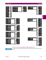
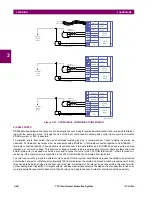
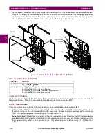
CONTACT INPUTS
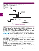
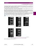
A dry contact has one side connected to terminal B3b. This is the positive 48 V DC voltage rail supplied by the power sup-
ply module. The other side of the dry contact is connected to the required contact input terminal. Each contact input group
has its own common (negative) terminal which must be connected to the DC negative terminal (B3a) of the power supply
module. When a dry contact closes, a current of 1 to 3 mA flows through the associated circuit.
A wet contact has one side connected to the positive terminal of an external DC power supply. The other side of this contact
is connected to the required contact input terminal. If a wet contact is used, then the negative side of the external source
must be connected to the relay common (negative) terminal of each contact group. The maximum external source voltage
for this arrangement is 300 V DC.
The voltage threshold at which each group of four contact inputs detects a closed contact input is programmable as
17 V DC for 24 V sources, 33 V DC for 48 V sources, 84 V DC for 110 to 125 V sources, and 166 V DC for 250 V sources.
Figure 3–17: DRY AND WET CONTACT INPUT CONNECTIONS
Wherever a tilde “~” symbol appears, substitute with the slot position of the module.
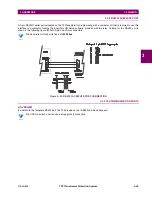
There is no provision in the relay to detect a DC ground fault on 48 V DC control power external output. We recommend
using an external DC supply.
827741A5.CDR
24 to 250 V
(Wet)
(Dry)
Contact input 1
Contact input 2
Contact input 3
Surge
Contact input 4
~7a
Common
~7b
~7c
~8a
~8b
~8c
Contact input 1
Contact input 2
Contact input 3
Surge
Contact input 4
~7a
Common
~7b
~7c
~8a
~8b
~8c
Control power
Surge
B5b
Filter
B8b
B6b
B6a
B8a
Critical failure
B1b
48 V DC output
B3b
B1a
B2b
B3a
HI+
LO+
Power supply module
Terminals from type 6B
contact input/output module
Terminals from type 6B
contact input/output module
NOTE
Summary of Contents for T35 UR Series
Page 10: ...x T35 Transformer Protection System GE Multilin TABLE OF CONTENTS ...
Page 48: ...2 18 T35 Transformer Protection System GE Multilin 2 2 SPECIFICATIONS 2 PRODUCT DESCRIPTION 2 ...
Page 314: ...5 192 T35 Transformer Protection System GE Multilin 5 10 TESTING 5 SETTINGS 5 ...
Page 338: ...6 24 T35 Transformer Protection System GE Multilin 6 5 PRODUCT INFORMATION 6 ACTUAL VALUES 6 ...
Page 350: ...7 12 T35 Transformer Protection System GE Multilin 7 2 TARGETS 7 COMMANDS AND TARGETS 7 ...
Page 366: ...8 16 T35 Transformer Protection System GE Multilin 8 2 CYBERSENTRY 8 SECURITY 8 ...
Page 406: ...A 14 T35 Transformer Protection System GE Multilin A 1 PARAMETER LISTS APPENDIX A A ...
Page 540: ...D 10 T35 Transformer Protection System GE Multilin D 1 IEC 60870 5 104 PROTOCOL APPENDIX D D ...
Page 552: ...E 12 T35 Transformer Protection System GE Multilin E 2 DNP POINT LISTS APPENDIX E E ...
Page 560: ...F 8 T35 Transformer Protection System GE Multilin F 3 WARRANTY APPENDIX F F ...


