


5-126
T35 Transformer Protection System
GE Multilin
5.5 FLEXLOGIC
5 SETTINGS
5
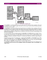
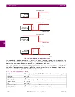
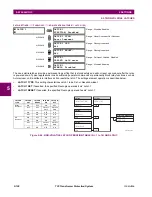
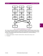
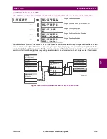
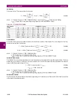
Figure 5–43: FLEXELEMENT INPUT MODE SETTING
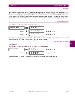
The
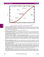
FLEXELEMENT 1 PICKUP
setting specifies the operating threshold for the effective operating signal of the element. If set
to “Over”, the element picks up when the operating signal exceeds the
FLEXELEMENT 1 PICKUP
value. If set to “Under”, the
element picks up when the operating signal falls below the
FLEXELEMENT 1 PICKUP
value.
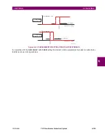
The
FLEXELEMENT 1 HYSTERESIS
setting controls the element dropout. It should be noticed that both the operating signal
and the pickup threshold can be negative facilitating applications such as reverse power alarm protection. The FlexElement
can be programmed to work with all analog actual values measured by the relay. The
FLEXELEMENT 1 PICKUP
setting is
entered in per-unit values using the following definitions of the base units:
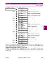
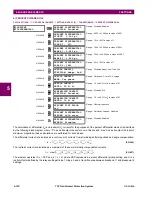
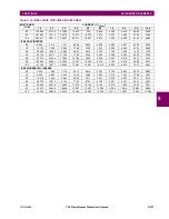
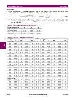
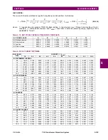
Table 5–13: FLEXELEMENT BASE UNITS
DCmA
BASE = maximum value of the
DCMA INPUT MAX
setting for the two transducers configured
under the +IN and –IN inputs.
DELTA TIME
BASE = 1 µs
FREQUENCY
f
BASE
= 1 Hz
PHASE ANGLE
ϕ
BASE
= 360 degrees (see the UR angle referencing convention)
POWER FACTOR
PF
BASE
= 1.00
RTDs
BASE = 100°C
SOURCE CURRENT
I
BASE
= maximum nominal primary RMS value of the +IN and –IN inputs
SOURCE POWER
P
BASE
= maximum value of V
BASE
×
I
BASE
for the +IN and –IN inputs
842706A2.CDR
FlexElement 1 OpSig
FLEXELEMENT 1 PKP
FLEXELEMENT
DIRECTION = Over;
FLEXELEMENT INPUT
MODE = Signed;
FlexElement 1 OpSig
FLEXELEMENT 1 PKP
FLEXELEMENT
DIRECTION = Over;
FLEXELEMENT INPUT
MODE = Absolute;
FlexElement 1 OpSig
FLEXELEMENT 1 PKP
FLEXELEMENT
DIRECTION = Under;
FLEXELEMENT INPUT
MODE = Signed;
FlexElement 1 OpSig
FLEXELEMENT 1 PKP
FLEXELEMENT
DIRECTION = Under;
FLEXELEMENT INPUT
MODE = Absolute;
Summary of Contents for T35 UR Series
Page 10: ...x T35 Transformer Protection System GE Multilin TABLE OF CONTENTS ...
Page 48: ...2 18 T35 Transformer Protection System GE Multilin 2 2 SPECIFICATIONS 2 PRODUCT DESCRIPTION 2 ...
Page 314: ...5 192 T35 Transformer Protection System GE Multilin 5 10 TESTING 5 SETTINGS 5 ...
Page 338: ...6 24 T35 Transformer Protection System GE Multilin 6 5 PRODUCT INFORMATION 6 ACTUAL VALUES 6 ...
Page 350: ...7 12 T35 Transformer Protection System GE Multilin 7 2 TARGETS 7 COMMANDS AND TARGETS 7 ...
Page 366: ...8 16 T35 Transformer Protection System GE Multilin 8 2 CYBERSENTRY 8 SECURITY 8 ...
Page 406: ...A 14 T35 Transformer Protection System GE Multilin A 1 PARAMETER LISTS APPENDIX A A ...
Page 540: ...D 10 T35 Transformer Protection System GE Multilin D 1 IEC 60870 5 104 PROTOCOL APPENDIX D D ...
Page 552: ...E 12 T35 Transformer Protection System GE Multilin E 2 DNP POINT LISTS APPENDIX E E ...
Page 560: ...F 8 T35 Transformer Protection System GE Multilin F 3 WARRANTY APPENDIX F F ...


