


5-186
T35 Transformer Protection System
GE Multilin
5.9 TRANSDUCER INPUTS AND OUTPUTS
5 SETTINGS
5
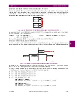
Figure 5–72: DCMA OUTPUT CHARACTERISTIC
The DCmA output settings are described below.
•
DCMA OUTPUT F1 SOURCE
: This setting specifies an internal analog value to drive the analog output. Actual values
(FlexAnalog parameters) such as power, current amplitude, voltage amplitude, power factor, etc. can be configured as
sources driving DCmA outputs. Refer to Appendix A for a complete list of FlexAnalog parameters.
•
DCMA OUTPUT F1 RANGE
: This setting allows selection of the output range. Each DCmA channel may be set inde-
pendently to work with different ranges. The three most commonly used output ranges are available.
•
DCMA OUTPUT F1 MIN VAL
: This setting allows setting the minimum limit for the signal that drives the output. This
setting is used to control the mapping between an internal analog value and the output current. The setting is entered
in per-unit values. The base units are defined in the same manner as the FlexElement base units.
•
DCMA OUTPUT F1 MAX VAL
: This setting allows setting the maximum limit for the signal that drives the output. This
setting is used to control the mapping between an internal analog value and the output current. The setting is entered
in per-unit values. The base units are defined in the same manner as the FlexElement base units.
The
DCMA OUTPUT F1 MIN VAL
and
DCMA OUTPUT F1 MAX VAL
settings are ignored for power factor base units (i.e. if
the
DCMA OUTPUT F1 SOURCE
is set to FlexAnalog value based on power factor measurement).
Three application examples are described below.
EXAMPLE: POWER MONITORING
A three phase active power on a 13.8 kV system measured via UR-series relay source 1 is to be monitored by the DCmA
H1 output of the range of –1 to 1 mA. The following settings are applied on the relay: CT ratio = 1200:5, VT secondary 115,
VT connection is delta, and VT ratio = 120. The nominal current is 800 A primary and the nominal power factor is 0.90. The
power is to be monitored in both importing and exporting directions and allow for 20% overload compared to the nominal.
The nominal three-phase power is:
(EQ 5.43)
The three-phase power with 20% overload margin is:
(EQ 5.44)
The base unit for power (refer to the FlexElements section in this chapter for additional details) is:
(EQ 5.45)
The minimum and maximum power values to be monitored (in pu) are:
(EQ 5.46)
The following settings should be entered:
842739A1.CDR
DRIVING SIGNAL
OUTPUT CURRENT
MIN VAL
I
min
I
max
MAX VAL
NOTE
P
3 13.8 kV 0.8 kA
×
0.9
×
×
17.21 MW
=
=
P
max
1.2 17.21 MW
×
20.65 MW
=
=
P
BASE
115 V 120
×
1.2 kA
×
16.56 MW
=
=
minimum power
20.65 MW
–
16.56 MW
------------------------------
1.247 pu, maximum power
20.65 MW
16.56 MW
---------------------------
1.247 pu
=
=
–
=
=
Summary of Contents for T35 UR Series
Page 10: ...x T35 Transformer Protection System GE Multilin TABLE OF CONTENTS ...
Page 48: ...2 18 T35 Transformer Protection System GE Multilin 2 2 SPECIFICATIONS 2 PRODUCT DESCRIPTION 2 ...
Page 314: ...5 192 T35 Transformer Protection System GE Multilin 5 10 TESTING 5 SETTINGS 5 ...
Page 338: ...6 24 T35 Transformer Protection System GE Multilin 6 5 PRODUCT INFORMATION 6 ACTUAL VALUES 6 ...
Page 350: ...7 12 T35 Transformer Protection System GE Multilin 7 2 TARGETS 7 COMMANDS AND TARGETS 7 ...
Page 366: ...8 16 T35 Transformer Protection System GE Multilin 8 2 CYBERSENTRY 8 SECURITY 8 ...
Page 406: ...A 14 T35 Transformer Protection System GE Multilin A 1 PARAMETER LISTS APPENDIX A A ...
Page 540: ...D 10 T35 Transformer Protection System GE Multilin D 1 IEC 60870 5 104 PROTOCOL APPENDIX D D ...
Page 552: ...E 12 T35 Transformer Protection System GE Multilin E 2 DNP POINT LISTS APPENDIX E E ...
Page 560: ...F 8 T35 Transformer Protection System GE Multilin F 3 WARRANTY APPENDIX F F ...


