


5-116
T35 Transformer Protection System
GE Multilin
5.5 FLEXLOGIC
5 SETTINGS
5
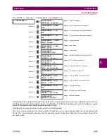
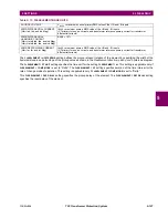
The operands available for this relay are listed alphabetically by types in the following table.
Table 5–10: T35 FLEXLOGIC OPERANDS (Sheet 1 of 5)
OPERAND TYPE
OPERAND SYNTAX
OPERAND DESCRIPTION
CONTROL
PUSHBUTTONS
CONTROL PUSHBTN 1 ON
CONTROL PUSHBTN 2 ON
CONTROL PUSHBTN 3 ON
CONTROL PUSHBTN 4 ON
CONTROL PUSHBTN 5 ON
CONTROL PUSHBTN 6 ON
CONTROL PUSHBTN 7 ON
Control pushbutton 1 is being pressed
Control pushbutton 2 is being pressed
Control pushbutton 3 is being pressed
Control pushbutton 4 is being pressed
Control pushbutton 5 is being pressed
Control pushbutton 6 is being pressed
Control pushbutton 7 is being pressed
DIRECT DEVICES
DIRECT DEVICE 1On
↓
DIRECT DEVICE 16On
DIRECT DEVICE 1Off
↓
DIRECT DEVICE 16Off
Flag is set, logic=1
↓
Flag is set, logic=1
Flag is set, logic=1
↓
Flag is set, logic=1
DIRECT INPUT/
OUTPUT
CHANNEL
MONITORING
DIR IO CH1 CRC ALARM
DIR IO CH2 CRC ALARM
DIR IO CH1 UNRET ALM
DIR IO CH2 UNRET ALM
The rate of direct input messages received on channel 1 and failing the CRC
exceeded the user-specified level
The rate of direct input messages received on channel 2 and failing the CRC
exceeded the user-specified level
The rate of returned direct input/output messages on channel 1 exceeded the
user-specified level (ring configurations only)
The rate of returned direct input/output messages on channel 2 exceeded the
user-specified level (ring configurations only)
ELEMENT:
Breaker arcing
BKR ARC 1 OP
BKR ARC 1 DPO
BKR ARC 2 OP
BKR ARC 2 DPO
Breaker arcing current 1 has operated
Breaker arcing current 1 has dropped out
Breaker arcing current 2 has operated
Breaker arcing current 2 has dropped out
BKR ARC 3 to 6
Same set of operands as shown for BKR ARC 1
ELEMENT:
Breaker control
BREAKER 1 OFF CMD
BREAKER 1 ON CMD
BREAKER 1
Φ
A BAD ST
BREAKER 1
Φ
A INTERM
BREAKER 1
Φ
A CLSD
BREAKER 1
Φ
A OPEN
BREAKER 1
Φ
B BAD ST
BREAKER 1
Φ
A INTERM
BREAKER 1
Φ
B CLSD
BREAKER 1
Φ
B OPEN
BREAKER 1
Φ
C BAD ST
BREAKER 1
Φ
A INTERM
BREAKER 1
Φ
C CLSD
BREAKER 1
Φ
C OPEN
BREAKER 1 BAD STATUS
BREAKER 1 CLOSED
BREAKER 1 OPEN
BREAKER 1 DISCREP
BREAKER 1 TROUBLE
BREAKER 1 MNL CLS
BREAKER 1 TRIP A
BREAKER 1 TRIP B
BREAKER 1 TRIP C
BREAKER 1 ANY P OPEN
BREAKER 1 ONE P OPEN
BREAKER 1 OOS
Breaker 1 open command initiated
Breaker 1 close command initiated
Breaker 1 phase A bad status is detected (discrepancy between the 52/a and
52/b contacts)
Breaker 1 phase A intermediate status is detected (transition from one
position to another)
Breaker 1 phase A is closed
Breaker 1 phase A is open
Breaker 1 phase B bad status is detected (discrepancy between the 52/a and
52/b contacts)
Breaker 1 phase A intermediate status is detected (transition from one
position to another)
Breaker 1 phase B is closed
Breaker 1 phase B is open
Breaker 1 phase C bad status is detected (discrepancy between the 52/a and
52/b contacts)
Breaker 1 phase A intermediate status is detected (transition from one
position to another)
Breaker 1 phase C is closed
Breaker 1 phase C is open
Breaker 1 bad status is detected on any pole
Breaker 1 is closed
Breaker 1 is open
Breaker 1 has discrepancy
Breaker 1 trouble alarm
Breaker 1 manual close
Breaker 1 trip phase A command
Breaker 1 trip phase B command
Breaker 1 trip phase C command
At least one pole of breaker 1 is open
Only one pole of breaker 1 is open
Breaker 1 is out of service
BREAKER 2 to 6
Same set of operands as shown for BREAKER 1
ELEMENT:
CT fail
CT FAIL PKP
CT FAIL OP
CT fail has picked up
CT fail has dropped out
ELEMENT:
Digital counters
Counter 1 HI
Counter 1 EQL
Counter 1 LO
Digital counter 1 output is ‘more than’ comparison value
Digital counter 1 output is ‘equal to’ comparison value
Digital counter 1 output is ‘less than’ comparison value
Counter 2 to 8
Same set of operands as shown for Counter 1
Summary of Contents for T35 UR Series
Page 10: ...x T35 Transformer Protection System GE Multilin TABLE OF CONTENTS ...
Page 48: ...2 18 T35 Transformer Protection System GE Multilin 2 2 SPECIFICATIONS 2 PRODUCT DESCRIPTION 2 ...
Page 314: ...5 192 T35 Transformer Protection System GE Multilin 5 10 TESTING 5 SETTINGS 5 ...
Page 338: ...6 24 T35 Transformer Protection System GE Multilin 6 5 PRODUCT INFORMATION 6 ACTUAL VALUES 6 ...
Page 350: ...7 12 T35 Transformer Protection System GE Multilin 7 2 TARGETS 7 COMMANDS AND TARGETS 7 ...
Page 366: ...8 16 T35 Transformer Protection System GE Multilin 8 2 CYBERSENTRY 8 SECURITY 8 ...
Page 406: ...A 14 T35 Transformer Protection System GE Multilin A 1 PARAMETER LISTS APPENDIX A A ...
Page 540: ...D 10 T35 Transformer Protection System GE Multilin D 1 IEC 60870 5 104 PROTOCOL APPENDIX D D ...
Page 552: ...E 12 T35 Transformer Protection System GE Multilin E 2 DNP POINT LISTS APPENDIX E E ...
Page 560: ...F 8 T35 Transformer Protection System GE Multilin F 3 WARRANTY APPENDIX F F ...


