P50 Agile P253
13 Technical Specifications
P253/EN M/C
13-7
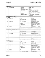
Operating Conditions
I.
Relative humidity
Humidity (RH) 95% maximum
II.
Operating temperature range
-25 ºC to +55 ºC
III.
Storage temperature range
-25 ºC to +70 ºC
Terminals Specification
I.
AC current input terminals
M5 threaded terminals for ring lug connection. Suitable up to 4 mm
2
II.
Auxiliary & input/output terminals M4 threaded terminal connection. Suitable up to 2.5 mm
2
III.
Tightening torque for M4/M5
screws
Maximum torque of 1.2 Nm
IV.
Rear communication terminal
Two wire connection. Suitable up to 2.5 mm
2
Mechanical & Environmental specification
I.
Design
Flush mounting case
II.
Weight
3.00 Kg approximate
III.
Pollution Degree
II
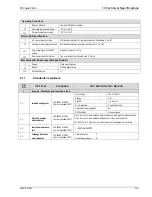
2.1.1
Standards Compliance
SR.
NO.
TYPE TEST
STANDARD
TEST SPECIFICATION / METHOD
1.
Impulse, Dielectric and Insulation tests
1.1
Impulse voltage test
IEC 60255-27:2005
(incl. corrigendum 2007)
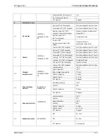
Test voltage
5kv, 1.2/50 µV
Energy
0.5 J
Polarity
+ve and –ve
No. of impulses
3 on each polarity
Duration between impulses
5s
EUT condition
Non energised
1.2
Dielectric voltage
withstand test
IEC 60255-27:2005
(incl. corrigendum 2007)
1) 2kV rms for 1 minute between all terminals connected together with case earth.
2) 2kV rms for 1 minute between independent circuits with case earth.
3) 1.5kV rms for 1 minute across open contacts of changeover output relays.
1.3
Insulation resistance
test
IEC 60255-27:2005
(incl. corrigendum 2007)
> 100 MΩ at 500V DC
1.4
Creepage distances
and clearances
IEC 60255-27:2005
(incl. corrigendum 2007)
Pollution degree : 2
Overvoltage category : III
Summary of Contents for P50 Agile P253
Page 3: ...P50 Agile P253 1 Introduction P253 EN M C 1 1 INTRODUCTION CHAPTER 1 ...
Page 4: ...1 Introduction P50 Agile P253 1 2 P253 EN M C ...
Page 11: ...SAFETY INFORMATION CHAPTER 2 ...
Page 12: ...Safety Information Pxxx 2 ...
Page 23: ...P50 Agile P253 3 Hardware Design P253 EN M C 3 1 HARDWARE DESIGN CHAPTER 3 ...
Page 24: ...3 Hardware Design P50 Agile P253253 3 2 P253 EN M C ...
Page 28: ...3 Hardware Design P50 Agile P253253 3 6 P253 EN M C E00276 Figure 2 Hardware design overview ...
Page 32: ...3 Hardware Design P50 Agile P253253 3 10 P253 EN M C ...
Page 33: ...P50 Agile P253 4 Front Panel P253 EN M C 4 1 FRONT PANEL CHAPTER 4 ...
Page 34: ...4 Front Panel P50 Agile P253 4 2 P253 EN M C ...
Page 39: ...P50 Agile P253 4 Front Panel P253 EN M C 4 7 Figure 2 USB port ...
Page 40: ...4 Front Panel P50 Agile P253 4 8 P253 EN M C ...
Page 41: ...P50 Agile P253 5 Configuration P253 EN M C 5 1 CONFIGURATION CHAPTER 5 ...
Page 42: ...5 Configuration P50 Agile P253 5 2 P253 EN M C ...
Page 154: ...5 Configuration P50 Agile P253 5 114 P253 EN M C ...
Page 155: ...P50 Agile P253 6 Protection Functions P253 EN M C 6 1 PROTECTION FUNCTIONS CHAPTER 6 ...
Page 156: ...6 Protection Functions P50 Agile P253 6 2 P253 EN M C ...
Page 182: ...7 Protection Parameter Settings P50 Agile P253 7 2 P253 EN M C ...
Page 203: ...P50 Agile P253 8 Monitoring Control P253 EN M C 8 1 MONITORING CONTROL CHAPTER 8 ...
Page 204: ...8 Monitoring Control P50 Agile P253 8 2 P253 EN M C ...
Page 222: ...8 Monitoring Control P50 Agile P253 8 20 P253 EN M C ...
Page 223: ...P50 Agile P253 9 SCADA Communications P253 EN M C 9 1 SCADA COMMUNICATIONS CHAPTER 9 ...
Page 224: ...9 SCADA Communications P50 Agile P253 9 2 P253 EN M C ...
Page 249: ...P50 Agile P253 10 Installation P253 EN M C 10 1 INSTALLATION CHAPTER 10 ...
Page 250: ...10 Installation P50 Agile P253 10 2 P253 EN M C ...
Page 260: ...11 Commissioning Instructions P50 Agile P253 11 2 P253 EN M C ...
Page 270: ...11 Commissioning Instructions P50 Agile P253 11 12 P253 EN M C ...
Page 272: ...12 Maintenance and Troubleshooting P50 Agile P253 12 2 P253 EN M C ...
Page 282: ...13 Technical Specifications P50 Agile P253 13 2 P253 EN M C ...
Page 292: ...13 Technical Specifications P50 Agile P253 13 12 P253 EN M C ...
Page 293: ...P50 Agile P253 14 Wiring Diagrams P253 EN M C 14 1 WIRING DIAGRAMS CHAPTER 14 ...
Page 294: ...14 Wiring Diagrams P50 Agile P253 14 2 P253 EN M C ...
Page 297: ......


