


P50 Agile P253
7 Protection Parameter Settings
P253/EN M/C
7-9
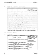
2.8
IO CONFIGURATION Settings
Sr. No
Parameter
Defaults setting
Setting/Ranges
1.
Password
0000
0000 to zzzz
This setting specifies to enter the set password
2.
Relay
Gen Strt*
654321
000000
6
RL6……..1
RL1
1 = assigned ; 0 = not assigned
This cell sets the output contact RL1 – RL6 for desired function.
3.
LED G
Gen Strt*
8765
0000
8
LED8……..5
LED5
1 = assigned ; 0 = not assigned
This cell sets the Green LED L5 – L8 for desired function.
4.
LED R
Gen Strt*
8765
0000
8
LED L8…..5
LED L5
1 = assigned ; 0 = not assigned
This cell sets the RED LED L5 – L8 for desired function.
5.
AND Logic
Gen Strt*
DCBA
0000
D
AND Logic D……..A
AND Logic A
1 = assigned ; 0 = not assigned
This cell sets the input for AND Logic equation (A, B, C and D).
6.
Opto I/P
Rem.Rst*
654321
000000
6
S6……..1
S1
1 = assigned ; 0 = not assigned
This cell sets the Opto I/P 1 – Opto I/P 6 for desired function.
*Note:
The functions which can be assigned to Output Relay, LED Green, LED RED, AND Logic
and Opto I/P are listed in Chapter 8: Monitoring and Control.
2.9
O/P RELAY CONFIG Settings
Sr. No
Parameter
Defaults setting
Setting/Ranges
1.
Password
0000
0000 to zzzz
This setting specifies to enter the set password
2.
Contact HR/SR
000000
1= HR / 0 = SR
This setting specifies the reset mechanism (manual/hand reset or self reset) for O/P relay contacts.
3.
O/P-1 Open Time
0.05 S
0s to 1s step of 0.01s
4.
O/P-2 Open Time
0.05 S
0s to 1s step of 0.01s
5.
O/P-3 Open Time
0.05 S
0s to 1s step of 0.01s
6.
O/P-4 Open Time
0.05 S
0s to 1s step of 0.01s
7.
O/P-5 Open Time
0.05 S
0s to 1s step of 0.01s
8.
O/P-6 Open Time
0.05 S
0s to 1s tep of 0.01s
This setting specifies the time duration for which the output contacts holds its state after non availability of the command to the O/P
contact.
9.
LED G HR/SR
0000
1= HR / 0 = SR
This setting specifies the reset mechanism (manual/hand reset or self reset) for Green LED.
10.
LED R HR/SR
0000
1= HR / 0 = SR
This setting specifies the reset mechanism (manual/hand reset or self reset) for RED LED.
11.
ANDEQ A Op Time
1 S
1s to 3600s step of 1s
12.
ANDEQ A Rst Time
1 S
1s to 3600s step of 1s
Summary of Contents for P50 Agile P253
Page 3: ...P50 Agile P253 1 Introduction P253 EN M C 1 1 INTRODUCTION CHAPTER 1 ...
Page 4: ...1 Introduction P50 Agile P253 1 2 P253 EN M C ...
Page 11: ...SAFETY INFORMATION CHAPTER 2 ...
Page 12: ...Safety Information Pxxx 2 ...
Page 23: ...P50 Agile P253 3 Hardware Design P253 EN M C 3 1 HARDWARE DESIGN CHAPTER 3 ...
Page 24: ...3 Hardware Design P50 Agile P253253 3 2 P253 EN M C ...
Page 28: ...3 Hardware Design P50 Agile P253253 3 6 P253 EN M C E00276 Figure 2 Hardware design overview ...
Page 32: ...3 Hardware Design P50 Agile P253253 3 10 P253 EN M C ...
Page 33: ...P50 Agile P253 4 Front Panel P253 EN M C 4 1 FRONT PANEL CHAPTER 4 ...
Page 34: ...4 Front Panel P50 Agile P253 4 2 P253 EN M C ...
Page 39: ...P50 Agile P253 4 Front Panel P253 EN M C 4 7 Figure 2 USB port ...
Page 40: ...4 Front Panel P50 Agile P253 4 8 P253 EN M C ...
Page 41: ...P50 Agile P253 5 Configuration P253 EN M C 5 1 CONFIGURATION CHAPTER 5 ...
Page 42: ...5 Configuration P50 Agile P253 5 2 P253 EN M C ...
Page 154: ...5 Configuration P50 Agile P253 5 114 P253 EN M C ...
Page 155: ...P50 Agile P253 6 Protection Functions P253 EN M C 6 1 PROTECTION FUNCTIONS CHAPTER 6 ...
Page 156: ...6 Protection Functions P50 Agile P253 6 2 P253 EN M C ...
Page 182: ...7 Protection Parameter Settings P50 Agile P253 7 2 P253 EN M C ...
Page 203: ...P50 Agile P253 8 Monitoring Control P253 EN M C 8 1 MONITORING CONTROL CHAPTER 8 ...
Page 204: ...8 Monitoring Control P50 Agile P253 8 2 P253 EN M C ...
Page 222: ...8 Monitoring Control P50 Agile P253 8 20 P253 EN M C ...
Page 223: ...P50 Agile P253 9 SCADA Communications P253 EN M C 9 1 SCADA COMMUNICATIONS CHAPTER 9 ...
Page 224: ...9 SCADA Communications P50 Agile P253 9 2 P253 EN M C ...
Page 249: ...P50 Agile P253 10 Installation P253 EN M C 10 1 INSTALLATION CHAPTER 10 ...
Page 250: ...10 Installation P50 Agile P253 10 2 P253 EN M C ...
Page 260: ...11 Commissioning Instructions P50 Agile P253 11 2 P253 EN M C ...
Page 270: ...11 Commissioning Instructions P50 Agile P253 11 12 P253 EN M C ...
Page 272: ...12 Maintenance and Troubleshooting P50 Agile P253 12 2 P253 EN M C ...
Page 282: ...13 Technical Specifications P50 Agile P253 13 2 P253 EN M C ...
Page 292: ...13 Technical Specifications P50 Agile P253 13 12 P253 EN M C ...
Page 293: ...P50 Agile P253 14 Wiring Diagrams P253 EN M C 14 1 WIRING DIAGRAMS CHAPTER 14 ...
Page 294: ...14 Wiring Diagrams P50 Agile P253 14 2 P253 EN M C ...
Page 297: ......


