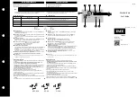
POWER
ZONE 1
LED
INDICATORS
FUSE
6 AMP
FUSE
6 AMP
SR 501-EXP-4
POWER
CONTROLS
SLAVE
PRIORITY ON
RESET
PRIMARY PUMP ON
POST PURGE ON
PRIORITY PROTECT ON
PUMP EXERCISE ON
30 SEC/2 WK
MASTER
OFF
OFF
OFF
OFF
OFF
NORMAL
4 MIN/24 HOUR
ACCESSORY
PORT
120 VAC
INPUT
CIRCULATOR
H
N/O
N
H
120 VAC
CIRCULATOR
PRIMARY
OUTPUT
N/C
INPUT
120 VAC
PRIMARY
CIRCULATOR
(OPTIONAL)
TO: "TT" on Boiler Aquastat
END
SWITCH
RESET
OVERRIDE
THERMOSTAT
EXPANSION
X
W
R
X
1
A
2
C
B
TO: DHW Aquastat if PC700
Boiler Reset is installed.
(See Page 2.)
T
24 VOLTS AC ONLY
C
SINGLE ZONE
EXPANDABLE SWITCHING RELAY
THERMOSTAT
See
NOTE
NOTE:
Resistor (1K
Ω
,
1
⁄
2
W)
may be needed between
W
and
C
terminals.
Operation:
When the thermostat calls for heat, the circulating pump
is energized and the isolated end switch (X and X) will start the boiler.
Priority Operation:
When the priority dip switch is set to ON and the
zone is actuated, all other connected zoning panels will stop operation
until the zone is satisfied. When the priority dip switch is set to OFF
and the zone is actuated, all other connected zoning panels will oper-
ate independently.
Mode Operation:
When the mode dip switch is set to NORMAL, the end
switch relay will be energized if any zone is in operation. When the mode
dip switch is set to RESET, the end switch relay will only be energized
through the operation of a plug-in reset control or closure of Priority Input.
Primary Pump Operation:
When the dip switch is set to OFF, the pri-
mary circulating pump output will not energize when zone calls for
heat. When the dip switch is set to ON, the primary circulating pump
output will energize when zone calls for heat.
Post Purge Operation:
When the dip switch is set to ON, the circula-
tion pump output will stay energized for 2 minutes after its thermostat
or aquastat is satisfied, but not operate the boiler.
Priority Protection Operation:
When the dip switch is set to ON and
the zone (priority) on master zone panel calls for heat continuously for
more than one hour, then power is returned to the space heating zones
allowing all the zones to function independently. Once the zone (pri-
ority) on master zone panel is satisfied, the control’s auto-reset is acti-
vated and the zone is again allowed to have priority for up to one hour.
Pump Exercise Operation:
When the dip switch is set to ON, the solid
state timer cycles all the circulating pumps that are attached to the
Expandable Switching Relay at the selected time interval. The time
interval can be set for the pumps to run for either 30 seconds every 2
weeks or for 4 minutes every 24 hours.
End Switch:
The switch closes when the thermostat calls for heat and
the mode switch is set to NORMAL. The end switch also closes when
the mode switch is set to RESET and a PC Series boiler reset power con-
trol is calling for heat.
Expansion Connections:
Set the expansion switch to MASTER on the
switching relay that has the designated priority zone or is utilizing the
PC Series plug-in option. Set all other daisy chained controls to SLAVE.
Using thermostat wire (18-22 gauge) connect between terminals A, B,
C on the master control to the corresponding A, B, C on the SLAVE
control(s). Controls may be daisy chained up to 20 zoning panels using
any combination of -EXP controls (120 zones if all are 6 zone panels).
Thermostat Input (24 vac):
R
Hot side of transformer. Connect to
R
on thermostat.
W
Switched
R
signal from thermostat. Connect to
W
on thermostat.
C
Common side of transformer. Connect to
COM
on
thermostat (optional).
120 VAC Connections (N is Neutral, H is Hot):
Power Input
Connect 120 Volt AC power.
Primary
Primary Pump (optional)
N/O Zone
Circulator Zone
N/C Zone
Normally closed terminal for the Circulator Zone.
Will deactivate on a thermostat call.
N
Connect to pump neutral leads.
WARNING:
Wiring connections must be made in accordance with all applicable
electrical codes. Use copper wire only. 120 VAC wiring must have a minimum
temperature rating of 75°C. Failure to follow this instruction can result in person-
al injury or death and/or property damage. 12-18 gauge wire recommended for
120 VAC connections, 14-22 gauge wire for thermostat connections, and 14-22
gauge wire for 24 VAC source connections.
Wiring Diagram:
Instruction Sheet
SR501-EXP-4 Switching Relay
102-385
SUPERSEDES: March 1, 2013
EFFECTIVE: December 20, 2013
Plant ID# 9300-2872
SLAVE
ZONE PRIORITY ON
RESET
PRIMARY PUMP FUNCTION ON
POST PURGE ON
PRIORITY PROTECTION ON
PUMP EXERCISE ON
30 SEC/2 WK
MASTER
OFF
NORMAL
OFF
OFF
OFF
OFF
4 MIN/24 HOUR
Dip Switch Settings:
Specifications:
PRODUCT
NUMBER
INPUT
MAXIMUM
TYPE 1 ENCLOSURE
NUMBER
OF ZONES
VOLTAGE
COMBINED LOAD
WIDTH
HEIGHT
DEPTH
SR501-EXP-4
1
120/60/1 VAC
12 amps
4
7
/
8
"
6
5
/
8
"
2
3
/
8
"
All circulator relay connections, including ZC/ZR, are rated
1
/
3
hp (6 FLA, 36 LRA) at 120 VAC.
The end switch connection is rated 24 VAC, 1 amp.
The thermostat connection supplies a 24 VAC class 2 output.
This device complies with part 15 of the FCC Rules. Operation is subject to the fol-
lowing two conditions: (1) This device may not cause harmful interference, and (2)
this device must accept any interference received, including interference that may
cause undesired operation.
Troubleshooting:
• Problem:
Digital thermostats do not work correctly when connected
to a switching relay.
• Solution:
Some thermostats are a “Power Stealing” type which means
they are powered by the switching relay with just 2 wires (
R
&
W
). A
resistor may be needed in order to have the thermostat work properly.
This resistor should be placed between the
W
&
C
(
common
) termi-
nals of the switching relay. If the thermostat manufacturer does not
supply a resistor, a 1000 ohm ½ watt resistor has proven to work with
most models and is readily available at electronic supply outlets (e.g.
8the batteries are fresh and installed correctly.
• Problem:
No heat in a zone or room of building.
• Solution:
LED diagnostic lights will help find a component that is
not working properly. The green LED should always be on, indicating
that power is connected and the solid-state fuse is good. When there
is a call for heat, the red LED will come on indicating power to the
zone circulator. This indicates the thermostat is working correctly. If
the red LED does not come on, then check the thermostat and ther-
mostat wiring for errors.
For information on Taco’s Switching Relays (SR)
including catalog sheet, instruction sheets, Visio
stencils and our highly praised Zone Controls
Wiring Guide, scan the QR code to the left or go
to our website: http://www.taco-hvac.com.