background image

CHAPTER 4:                                                                          THE DDFR AND RELAY INFORMATIONCONFIGURING THE EXTERNAL WATCHDOG

DISTRIBUTED DIGITAL FAULT RECORDER – INSTRUCTION MANUAL

79

The above settings screen shows a UR device configured to receive an External WatchDog 
at VI 8 and a DriveSpace Watchdog at VI 9. 

The Function setting must be enabled and the Type setting is set to Self-Reset. 

The Virtual Input Name is changed to reflect the type of WatchDog being received. 

The Events for VI 9 are enabled so that the DriveSpace event can be captured in the UR’s 
Event Record.  The Events for VI 8 are disabled because the External WatchDog command 
is sent by the DDFR at a continuous interval with each command creating an entry in the 
UR’s Event Record.

4.2.3.2 FlexLogic

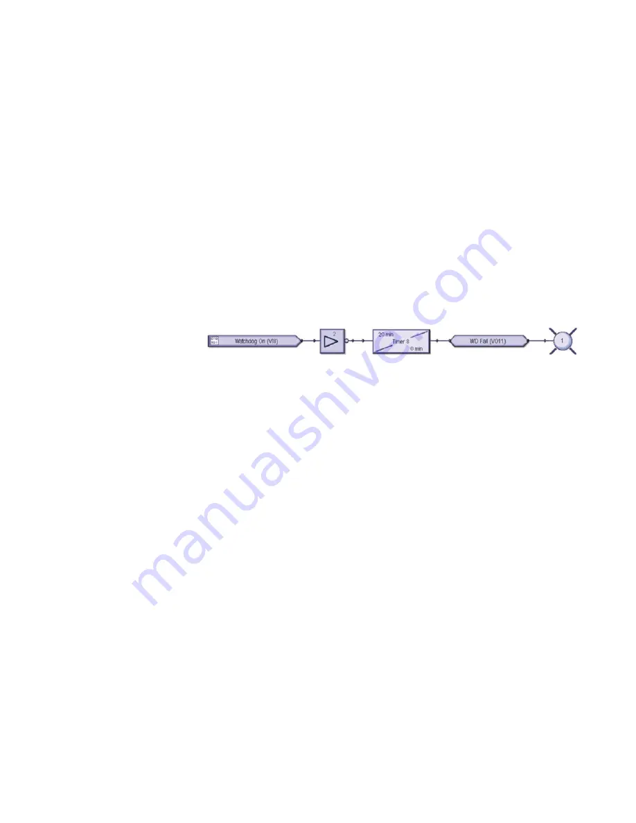
To complete the WatchDog logic, a FlexLogic equation needs to be created. An example of 
the FlexLogic is shown in Figure 2-16.  If the DDFR is configured to send an External 
Watchdog every 10 minutes, then the timer is set for 20 minutes.  When the timer 
completes its countdown, logic should be triggered to indicate that the DDFR requires 
attention; in this example it’s Virtual Output 11. This timer circuit will also restart the 
countdown each time the Virtual Input command is received (VI 8).

FIGURE 4–11: FlexLogic equation (designed using Viewpoint Engineer 2.20)

In the above example, when the UR relay fails to receive the External WatchDog from the 
DDFR, Virtual Output #11 will go high which will then turn ON User Programmable LED #1.

Summary of Contents for Multilin DDFR

Page 1: ...222 Fax 905 201 2098 Internet http www GEmultilin com GE Multilin s Quality Management System is registered to ISO9001 2000 QMI 005094 1601 9024 A1 DDFR Distributed Digital Fault Recorder Instruction Manual Software Revision 2 0x Manual P N 1601 9024 A2 Manual Order Code GEK 113333A Copyright 2007 GE Multilin ...

Page 2: ...ocal codes and ordinances because they vary greatly 2007 GE Multilin Incorporated All rights reserved GE Multilin Distributed Digital Fault Recorder instruction manual for revision 2 0x Distributed Digital Fault Recorder and DDFR are registered trademarks of GE Multilin Inc The contents of this manual are the property of GE Multilin Inc This documentation is furnished on license and may not be rep...

Page 3: ......

Page 4: ......

Page 5: ...19 USING THE DISCOVER DDFR BUTTON 28 SETTING UP ARCHIVER COMMUNICATION 32 SETTING UP RELAY TO DDFR COMMUNICATION 34 ATTACHING FIELD DEVICES RELAYS TO THE DDFR 34 Attaching Ethernet based Relays 34 Attaching RS485 based Relays 35 Attaching RS232 based Relays 36 Attaching Multiple Relay Communication Types to the DDFR 36 2 PRODUCT DESCRIPTION OVERVIEW 37 BENEFITS OF DISTRIBUTED VS CENTRALIZED DIGITA...

Page 6: ...ING THE DDFR WATCHDOGS 65 TYPES OF WATCHDOG 66 THE DDFR INTERNAL WATCHDOG 66 THE DRIVESPACE WATCHDOG 67 DriveSpace WatchDog Alarms 67 Adding a DriveSpace WatchDog 68 4 THE DDFR AND RELAY INFORMATION RELAY INFORMATION 71 ACTUAL VALUES RECORDS IN THE DDFR SETUP PROGRAM 71 Viewing Event Records 72 Viewing Waveform Records 72 Viewing Data Logger Records UR Relays Only 73 View Archiver Actual Values 74...

Page 7: ... ARCHIVER 88 ARCHIVER RECORDS GENERAL 88 ARCHIVER EVENTS RECORDS 88 ARCHIVER WAVEFORMS RECORDS 91 Waveform File Access 92 Waveform Merge 93 Waveform Resample 95 Viewing Retrieved Waveform Files 95 Waveform Cursor Times 96 Viewing Phasors 97 Viewing Harmonics 99 ARCHIVER DATA LOGGER RECORDS 100 Viewing the Retrieved Data Logger Files 102 Storage of Data Logger Records 102 6 MISCELLANEOUS CHANGE NOT...

Page 8: ...TOC IV DISTRIBUTED DIGITAL FAULT RECORDER INSTRUCTION MANUAL TABLE OF CONTENTS ...

Page 9: ...r Industrial Multilin GettingStarted 1 1 Ordering 1 1 1 Ordering the DDFR Select the basic model and the desired features from the selection guide below Table 1 1 Ordering Codes DDFR HI 120 to 230 VAC 110 to 250 VDC LO 24 to 48 VDC HI Redundant 120 to 230 VAC 110 to 250 VDC LO Redundant 24 to 48 VDC XX No redundant power supply ...

Page 10: ...able data from the GE relays currently operating in your facility so that it can be used conveniently and effectively The DDFR is in fact a highly effective data management device 1 2 2 1 Background Enhancements to the fault and disturbance recording abilities of modern microprocessor based protection relays has eliminated the need to install costly equipment whose sole purpose is to record inform...

Page 11: ...s stored with a name that includes the exact date and time at which the record was initially triggered If the Transient Fault record was originally recorded in the relay as a COMTRADE file the DDFR stores this record in its native format if the protection relay stores its record in another format such as a CSV file the DDFR automatically converts this file into the COMTRADE 1999 format so that the...

Page 12: ...contact GE Multilin immediately 1 2 4 Using this Manual This manual is designed with the assumption that you may or may not know about the principles of DDFR usage or EnerVista software in general If you know little about DDFR usage please read carefully what is written below bearing in mind that GE Multilin is available to fully support your questions about any aspect of the product If this is no...

Page 13: ...t can be used for fresh setup and or configuration of a new DDFR see chapter 3 but its main function is to act as the sole communication port for data from all the relays in your facility to the DDFR unit and from this unit to your computer For examples of typical connections from your relays to the DDFR unit and your computer see chapter 4 In addition you can communicate with any of your installe...

Page 14: ...6 DISTRIBUTED DIGITAL FAULT RECORDER INSTRUCTION MANUAL ABOUT YOUR NEW DDFR UNIT CHAPTER 1 GETTING STARTED Dimensions ...

Page 15: ...software can be used as always online or offline to configure monitor maintain and troubleshoot the operation of individual relay functions The EnerVista DDFR Setup software operates as follows The EnerVista DDFR Setup program communicates to the DDFR through the Ethernet port located on the DDFR see section 1 1 5 above If the DDFR is connected to an Ethernet Switch the EnerVista Setup software si...

Page 16: ...ly on your computer and 2 effective archival of potentially large amounts of data from DDFRs in the field Pentium class or higher processor Pentium II 300 MHz or better recommended Microsoft Windows Professional Windows 2000 Server Windows 2003 Server Windows XP Professional 0 5 GB of RAM minimum 256 MB recommended 100 GB hard disk space minimum 200 MB recommended 1 3 3 Setting Up the EnerVista So...

Page 17: ...utton on the main EnerVista Launchpad screen to open the IED Setup Z Click the Add Product button to open the Add Product dialog Z Click the from CD radio button at the top of the window Z Select the DDFR from the Add Product window as shown above Z Click the Add Now button to install the DDFR Setup Software then follow the installation instructions ...

Page 18: ...TTING STARTED Z Once the DDFR Setup is installed the DDFR icon will appear in the IED Setup window as shown on the right hand side of figure 1 3 below Note If at any time you are updating the DDFR software select the Web radio button to ensure the most recent software release FIGURE 1 3 Launchpad IED Setup window ...

Page 19: ...een of your PC click the Start button Z Select Programs Accessories Command Prompt The black DOS screen will appear Z Type ipconfig and press Enter A window similar to the one shown below will appear Z If your ipconfig screen shows a single Ethernet Adaptor proceed to section 1 4 2 Z If your IP Address is 192 168 2 n and the Subnet Mask is 255 255 n 0 go ahead and directly Discover the new DDFR go...

Page 20: ... and configure each directly from your computer Z Connect each DDFR unit to your computer individually using a small local PC type Ethernet switch box Z Set up its Ethernet communication parameters according to the procedure shown below section 1 4 3 In either of the above cases once each DDFR is set up to communicate you can immediately continue to configure the settings for that DDFR See Chapter...

Page 21: ...ured immediately to ensure that Network IP address conflicts do not occur To reconfigure the DDFR network parameters in your new DDFR Z Press the DDFR Setup button at the top left of the screen or alternatively select Communications DDFR Setup from the main menu to open the DDFR Setup Screen as shown in figure 1 4 below FIGURE 1 4 DDFR Setup Screen Table 1 3 Default DDFR IP Configuration IP Addres...

Page 22: ...the only one a DDFR Configuration Tool will appear as shown below Z Click Yes to launch the Configuration Tool Use the DDFR Configuration Tool to set the IP address of this DDFR to a valid IP address to be used within the domain of your network Z Input the new IP Address Subnet Mask and Default Gateway parameters into the DDFR Configuration Tool Note You must configure the new DDFR with a valid IP...

Page 23: ...CHAPTER 1 GETTING STARTED SETTING UP COMPUTER TO DDFR ETHERNET COMMUNICATIONS DISTRIBUTED DIGITAL FAULT RECORDER INSTRUCTION MANUAL 15 Z Press GO Z Press Yes to confirm the IP configuration ...

Page 24: ...ck synchronization Z Press OK The DDFR Setup screen will remain Note If for any reason firewall network configuration etc you cannot Discover a DDFR you can manually add it into the DDFR environment using DDFR Setup provided you know the IP Address of the DDFR unit To add a DDFR manually proceed as follows Z Click the Add DDFR button to define the new DDFR The newly configured DDFR appears as show...

Page 25: ...transfer the Order Code and firmware Version number from the DDFR If a communications error occurs ensure that the Ethernet communications values correspond to the actual assigned setting values Z If you wish to give the DDFR a new name insert the new name in the DDFR Name field then click OK The new name will be saved in the DDFR Note If you have already assigned a meaningful name to the DDFR and...

Page 26: ...N MANUAL SETTING UP COMPUTER TO DDFR ETHERNET COMMUNICATIONS CHAPTER 1 GETTING STARTED Z The new device will be added to the DDFR Site List located on the upper left side of the main EnerVista DDFR Setup screen FIGURE 1 5 DDFR Site List Online Window ...

Page 27: ...ed for Ethernet communication 1 4 4 Setting up with Multiple NIC If your DDFR Setup cannot Discover the factory configured DDFR unit and you hav multiple NICs in your DDFR Setup computer please proceed as follows Z Select Control Panel Network and Dial up Connections Z Select Local Area Connection Z Select Protocol Z Select Internet Protocol TCP IP then press Properties A window similar to the one...

Page 28: ...n your IP Address Subnet Mask and Default Gateway as well as your Preferred and Alternate DNS servers Z Click on the Use the following IP address radio button if you have a dynamic IP Address Z Write the IP Address settings shown below in the appropriate boxes You can leave the DNS Server section empty Z Press OK Z Launch the EnerVista DDFR Setup program Z Click on the DDFR Setup button The DDFR S...

Page 29: ...RNET COMMUNICATIONS DISTRIBUTED DIGITAL FAULT RECORDER INSTRUCTION MANUAL 21 Z Press the Discover DDFRs button Once the Setup program has competed its routine the window will show the discovered DDFRs and a warning window will appear as shown below Z Press Yes ...

Page 30: ...IP Address which has to be changed Z At the top right side of the window type a name and a description for the DDFR The Order Code and Version fields at the bottom of the window will be filled in automatically when the DDFR is discovered Z Press OK The main EnerVista DDFR screen will now show the newly discovered DDFR along with any existing DDFRs Z Expand the menu for this DDFR by clicking on its...

Page 31: ...e Configure IP option Z When asked Are you sure you want to change the DDFR s IP Address configuration press the Yes button The DDFR IP Configuration window shown above will appear Z Using the IP Address Subnet Mask and Default Gateway information given to you by your IT department fill in this information on the IP Configuration window Z Press OK ...

Page 32: ...ation window as shown at the bottom right of the above image Z Click the Cancel button Go back to the Internet Protocol TCP IP window as follows Z Select Control Panel Network and Dial up Connections Z Select Local Area Connection Z Select Protocol Z Select Internet Protocol TCP IP then press Properties Z Restore your original computer IP configuration In the example above dynamic automatic IP add...

Page 33: ...S DISTRIBUTED DIGITAL FAULT RECORDER INSTRUCTION MANUAL 25 Z On the main EnerVista DDFR Setup screen click on the DDFR Setup button The DDFR Setup window will appear Z Highlight the DDFR you have just installed Z Press the Delete button The following Warning window will appear ...

Page 34: ...UAL SETTING UP COMPUTER TO DDFR ETHERNET COMMUNICATIONS CHAPTER 1 GETTING STARTED Z Click on Yes Z On the DDFR Setup screen press the Discover DDFRs button After a short time a message window will appear indicating information about your discovered DDFR s ...

Page 35: ...ICATIONS DISTRIBUTED DIGITAL FAULT RECORDER INSTRUCTION MANUAL 27 Z Click OK Z Check out your DDFRs to ensure that none of them contain the original factory installed IP Address You can now go ahead and configure the new DDFR for the relays to which it will be connected ...

Page 36: ... will appear which indicates how many new DDFRs were found and how many were added to the system Note The Discover feature may not work in network configurations where firewalls and or routers are between the DDFR Setup and the DDFRs The Discover feature uses UDP and broadcasts a UDP enquiry packet to which the DDFRs respond To use the Discover feature the procedure is as follows Once all the new ...

Page 37: ...INSTRUCTION MANUAL 29 Z Press the DDFR Setup button at the top left of the EnerVista DDFR Setup screen The DDFR Setup window will appear as shown Note that in the above DDFR Setup window there are no DDFRs listed under the DDFR menu heading Z Press the Discover DDFR button at the top left of the DDFR Setup window ...

Page 38: ... changed to parameters supplied by your IT Department Other changes may be made to existing Ethernet parameters if you need to revise these parameters Z For each DDFR press the Read Order Code button to automatically insert the appropriate DDFR Order Code and Version number Note If you have already assigned a meaningful name to the DDFR and you press the Read Order Code button the name will be cha...

Page 39: ...TRIBUTED DIGITAL FAULT RECORDER INSTRUCTION MANUAL 31 Expanding the DDFRs shows the configuration parameters The newly set up DDFRs are now ready to have their relay settings configured Note For information on configuring DDFR relay settings please refer to Chapter 3 of this manual ...

Page 40: ...ER 1 GETTING STARTED 1 4 6 Setting up Archiver Communication Z Click on the the DDFR Setup button to show the DDFR Setup window Z Click on the DDFR Archivers tree item Z Click on the Add button Z Fill in the Archiver s IP Address Z Press the Read Order Code button The Archiver will be assigned a name by the system ...

Page 41: ... press the OK button to save the setup Note If you do not have easy access to your Archiver PC IP Address you can get it as follows Z On the main Windows screen select Start Programs Accessories Command Prompt Z On the black Command Prompt screen type ipconfig A block of text will appear Z Note down the IP Address shown this is the IP Address of the Archiver located on this particular computer ...

Page 42: ...ilin s MultiNet converter for example to convert to Ethernet from a variety of other communication types Once all communication types have been converted to Ethernet this way at least one MultiLink Ethernet switch will be necessary to allow you to 1 connect the computer via Ethernet to the DDFRs for configuration and or data collection purposes and 2 assemble all Ethernet relay outputs from origin...

Page 43: ...1 GETTING STARTED SETTING UP RELAY TO DDFR COMMUNICATION DISTRIBUTED DIGITAL FAULT RECORDER INSTRUCTION MANUAL 35 1 5 1 2 Attaching RS485 based Relays FIGURE 1 9 Typical RS485 based DDFR to Relay Communications ...

Page 44: ...ELAY TO DDFR COMMUNICATION CHAPTER 1 GETTING STARTED 1 5 1 3 Attaching RS232 based Relays FIGURE 1 10 Typical RS232 based DDFR to Relay Communications 1 5 1 4 Attaching Multiple Relay Communication Types to the DDFR FIGURE 1 11 Typical DDFR to Relay Mixed Communications ...

Page 45: ...E Consumer Industrial Multilin ProductDescription 2 1 Overview 2 1 1 Benefits of Distributed vs Centralized Digital Fault Recording Figures 2 1 and 2 2 show the substation wiring method data collection and communication architecture for a centralized Digital Fault Recorder versus that of a Distributed Digital Fault Recorder ...

Page 46: ...h measurement taken The internal recording systems integral to GE Multilin relays are not used FIGURE 2 1 Centralized Digital Fault RecorderSystem 2 1 1 2 Distributed DFR System DDFR In the distributed DFR DDFR the data recording facilities already built into the GE Multilin protection relays record all information This data is retrieved by the station DDFR s and stored and processed for analysis ...

Page 47: ...the PC based DDFR Archiver The DDFR thus affords you the opportunity to make full use of the disturbance data collection facility designed into your relays Such data is automatically sent to the DDFR upon preset triggering of events monitored by each of your relays 2 1 2 1 The Distributed Digital Fault Recorder DDFR Records archives and provides analysis of power system disturbance data recorded i...

Page 48: ...des a method for archiving the data stored locally in the DDFR hardware to a PC based Archiver see below providing permanent data storage and hence system wide disturbance analysis at your convenience 2 1 2 2 The DDFR Archiver The Archiver is used to automatically archive in a central usually remote location the data collected in DDFRs distributed throughout the power system This tool provides you...

Page 49: ...lay Firmware Versions Relay Series Relay Firmware Level s Supported SR 750 760 3 6x 7 0x 469 2 5x 5 0x 745 2 4x 5 0x 489 1 3x 4 0x UR B30 2 6x 5 2x B90 3 0x 4 9x C30 2 6x 5 2x C60 2 6x 5 2x C70 5 2x D30 3 0x 5 2x D60 2 6x 5 2x F35 2 6x 5 2x F60 2 6x 5 2x G30 4 4x 5 2x G60 2 8x 5 2x L60 2 6x 5 2x L90 2 6x 5 2x M60 2 6x 5 2x N60 3 4x 5 2x T35 2 8x 5 2x T60 2 6x 5 2x 650 F650 1 60 3 40 ...

Page 50: ...ional Redundant Power Supplies As above Hard Drive Type Flash hard drive Hard Drive Capacity Total of 8 Gigabytes storage minimum Cooling Convection fanless Ethernet Ports 1 rear 100Mbit copper Ethernet port Indicators Single front LED green indicating power to DDFR Standards Conformance to all standard IEEE and IEC specifications for substation devices RELAY SUPPORT UR family of relays B30 C30 C6...

Page 51: ...22 3 ANSI C37 90 2 Envelop port 10 V m 35 V m Fast Transient IEC 60255 22 4 ANSI C37 90 1 Power supply and outputs 4 kV 2 5 kHz Communication ports 2 kV 5 kHz Surge Immunity IEC 60255 22 5 IEC 61000 4 5 Line to line 0 5 1 0 kV Line to Earth 0 5 1 0 2 0 kV Conducted Immunity IEC 60255 22 6 IEC 61000 4 6 Severity level 10 Vemf Severity level 10 Vemf Power Frequency Magnetic Field IEC 61000 4 8 1 sec...

Page 52: ...ating 32 front 2 3 4 Approvals and Certification CERTIFICATION CE LVD 73 23 EEC CE EMC 81 336 EEC EMC TESTS Electrostatic Discharge Air and Direct EN IEC60255 22 2 1997 EN IEC1000 4 2 1995 8KV air and 6KV Contact Electrical Fast Transient Burst Immunity Capacitive Clamp EN IEC60255 22 4 2002 EN IEC10004 4 2004 2KV 5Khz 4KV 2 5Khz failed at 4KV IEEE ESD IEEE C37 90 3 2001 8KV Surge Immunity EN IEC6...

Page 53: ...s EN 61000 6 4 2001 CISPR22 EN IEC 60255 25 2000 ETP 6 2 6 7 Class A ENVIRONMENTAL TESTS Relative Humidity Cyclic EN IEC 60068 2 30 2005 95 6days Cold Temperature EN IEC 60068 2 1 1990 1993am 20 deg C cold start up Dry Heat Temperature EN IEC 60068 2 2 1994 1993am 1994am 70deg C hot start up MECHANICAL TESTS Shock 2 Bump EN IEC 60255 21 2 1996 Class 1 FUNCTIONAL TESTS Voltage Effects Over Voltage ...

Page 54: ...46 DISTRIBUTED DIGITAL FAULT RECORDER INSTRUCTION MANUAL SPECIFICATIONS CHAPTER 2 PRODUCT DESCRIPTION ...

Page 55: ... DDFR Setup has password protection that limits individual access to the DDFR units you must set up your password before you attempt to go online to configure the individual DDFRs on your system By default the security functionality in the DDFR Setup is set to OFF 3 1 2 Password Accessibility Groups The DDFR system operates with several default password accessibility groups Individuals added to th...

Page 56: ...e DDFR unit using either a direct connection connected via an Ethernet cable to the configuring computer on the bench or desktop or an indirect connection the DDFR connected to an existing system and the configuring computer connected to this system via a GE MultiLink switch The latter is the more convenient approach 3 1 4 2 Multiple DDFR Units You can configure the relay settings for each DDFR di...

Page 57: ...omplete sets of preset configuration parameters Settings Files can be done while the computer and DDFR unit are connected to the system ie online that is parameters are transferred to each DDFR unit immediately saving these parameters on the computer in the process or with the DDFR units disconnected ie offline that is saved on the computer then transferred to the respective DDFRs at a later more ...

Page 58: ...tup Software 3 2 1 The EnerVista DDFR Menu Bar The EnerVista DDFR Setup Software menu bar layout is similar to that used by all EnerVista Setup applications FIGURE 3 1 EnerVista DDFR Setup Software Menu Bar 3 2 2 Enervista DDFR Online and Offline Window Structures tin FIGURE 3 2 DDFR Online and Offline Windows DDFR Online Window DDFR Offline Window ...

Page 59: ...an communicate directly for settings configuration and data interrogation The DDFRs listed in this window are arranged in a menu tree format each of which can be expanded to display the menu categories and items available for that DDFR There are 5 main menu header categories in the Online window Device Definition Settings Commands Actual Values and Maintenance The Device Definition menu displays i...

Page 60: ...e DDFR settings can be changed the DDFR Lock Unlock status has to be set to Unlock Once you have changed any DDFR settings the Lock Unlock status should be reset to Lock Before closing the EnerVista DDFR Setup application make sure the DDFR status is Lock Device Setup Click to configure new relays or change the configuration of existing relays attached to this DDFR This dialog appears in a separat...

Page 61: ...ng you to select which records and information to view for interrogating data Events Click to view the DDFR Event viewer in a separate window Most recent 300 to 500 events per device depending on number of devices configured in the DDFR unit Waveforms Click to view a listing of Waveforms in the right hand section of the main window Click on any Waveform to see a COMTRADE view of that Waveform Most...

Page 62: ...nu The Maintenance menu contains a method for updating the firmware on the DDFR and for changing the IP Address configuration Configure IP Click to change the IP address of the DDFR Update Firmware Click for a dialog that allows you to access the file containing the new DDFR firmware version that you previously downloaded FIGURE 3 8 The Maintenance Menu ...

Page 63: ...e when the DDFR Archivers menu is expanded as shown the Device Definition is displayed in much the same way as the DDFR itself From this Online Window you can access the Archiver and view Events Waveforms and DataLogger information archived in the Archiver Z Click on Events This Data Selection dialog box appears when each of the above three Actual Values items is clicked This allows you to be quit...

Page 64: ...DDFR SETUP SOFTWARE CHAPTER 3 DDFR CONFIGURATION Note Selecting Events brings up the Archiver Sequence of Events screen in a separate window see section 5 whereas when Waveforms and Data Logger are selected a list is displayed on the right hand window of the main DDFR screen ...

Page 65: ...by the person who created it Other relays can easily be added to this screen ie this Settings File as shown in section 3 3 3 below What all these relays have in common as stated above is that they communicate with this single DDFR and are thus defined in this single Settings File which is dedicated exclusively to that DDFR 3 3 2 Using Settings Files As indicated above a DDFR Settings File is sent ...

Page 66: ...y of referring to the fresh and preset configuration techniques discussed in section 3 1 4 3 3 3 3 Creating a New Settings File The EnerVista DDFR Setup Software allows you to create new Settings Files independent of a connected DDFR device in other words in off line or preset mode These can be transferred to the DDFR at a later time The following procedure illustrates how to create new Settings F...

Page 67: ...lays to a DDFR Settings File Each DDFR unit can accommodate up to 50 relays of various types so the ability to add or associate relays to DDFRs on demand is important These new relays may have just been installed in the plant environment or they could be existing relays possibly even connected to the plant communication network that it has been decided will be associated with the respective DDFRs ...

Page 68: ...lly transfer the Order Code and Version Z Click OK when complete 3 3 5 Upgrading Settings Files to a New DDFR Firmware Revision After the firmware for a DDFR has been upgraded it is necessary to upgrade the revision code contained in its associated Settings File This is illustrated in the following procedure Z In the Offline Window expand the Files menu if necessary Z Highlight the DFR Settings fi...

Page 69: ...se the following procedure to transfer and save Settings Files from a DDFR unit to a local computer Z Create a new empty Settings File for the desired DDFR unit using the procedure in section 3 3 3 Associate this Settings File with the desired DDFR unit Z Once this new Settings File DFR shows on the File List Offline Window expand its menu fully Z Select the Update file from DDFR menu item to obta...

Page 70: ...gs File with a revision number that does not match the DDFR firmware If the firmware has been upgraded since saving the Settings File see Upgrading Settings Files to a New DDFR Firmware Revision section 3 3 4 for instructions on changing the revision number of a Settings File The following procedure illustrates how to load settings to a DDFR unit from a file created offline see section 2 5 1 1 Bef...

Page 71: ...between the target device and the settings file the data will be transferred to the DDFR 3 3 9 Printing Settings and Actual Values The EnerVista DDFR Setup Software allows you to print partial or complete lists of settings and actual values Use the following procedure to print a list of settings Z Select a previously saved Settings File DFR in the Files Offline window Z From the main window menu s...

Page 72: ...he content of the Settings File for that DDFR will appear in the Device View window on the right hand side of the main screen as shown Z Select Print Zoom or Close from the menu buttons at the top of this window Settings lists can be printed in the same manner by right clicking on the desired file in the file list or device in the device list and selecting the Print Device DDFR Information or Prin...

Page 73: ... Screen The DDFR WatchDogs Screen figure 3 10 can be accessed using the Settings WatchDogs menu option in the Online Device Tree as shown in Figure 3 11 FIGURE 3 11 Online Device Tree Showing Settings Watchdog Option Watchdog information can also be accessed from the Settings Files in the Offline menu As with all Settings Files information WatchDog information can be created off line in the Settin...

Page 74: ...FR s used storage space is nearing maximum capacity Once the used storage space meets a certain threshold automated maintenance occurs and the oldest records deleted External WatchDog Notifies a UR relay that the DDFR is running For UR relays the External Watchdog causes an action to be performed to notify management of a DDFR not running situation In the UR relay the Internal Watchdog discussed a...

Page 75: ...t of this removal process that has not previously been archived to the central archiving system The Archiver is discussed in chapter 5 of this manual During the data erasing process the DDFR checks the date of the oldest Waveform Fault record the date of the oldest Data Logger record UR relays only and the date of the oldest Event on the Merged Events record The DDFR then erases the oldest piece o...

Page 76: ...3 2 Adding a DriveSpace WatchDog A DriveSpace WatchDog must be configured in both the DDFR and the UR relay intended as the receiver of the WatchDog The following will show the configuration of a DriveSpace WatchDog within the DDFR Z Press the Insert key on your keyboard Each time you press this key you will add a line to the External section of the WatchDog window as shown in Figure 3 13 Z Each t...

Page 77: ...xternal or DriveSpace on the device relay selected by clicking on the Type pull down list as shown in Figure 3 15 FIGURE 3 15 List of Types of WatchDog Note The same Virtual Input on a UR device cannot be used as both an External WatchDog and a DriveSpace WatchDog Note A maximum of three DriveSpace WatchDogs can be configured Z Select the frequency of sending out each WatchDog 10 30 or 60 minutes ...

Page 78: ...70 DISTRIBUTED DIGITAL FAULT RECORDER INSTRUCTION MANUAL CONFIGURING THE DDFR WATCHDOGS CHAPTER 3 DDFR CONFIGURATION ...

Page 79: ... Chapter 5 discusses Archived Values which consist of ALL the event values transferred from the DDFRs to the Archiver during a given long term time period The Actual Values of any DDFR unit viewable in the DDFR Setup Program are a segment of the latest Event Waveform and Data Logger values retrieved by each of the installed DDFRs Actual Values could therefore be considered a snapshot of some of th...

Page 80: ...RE 4 2 Event Viewer 4 1 1 2 Viewing Waveform Records Z Double Click on the Actual Values Waveforms tree item A view appears in the Main window that lists the latest Waveforms see section 3 2 3 1 stored in the DDFR These Waveforms are itemized by name and the date and time on which they occurred You can scroll through the list of Waveforms if they cannot all fit on a single screen Z Click on a part...

Page 81: ... the same as Waveform Records the only difference being that DataLogger Records are retrieved from relays can be significantly longer than Waveform Records Z Double Click the Actual Values Data Logger tree item A view appears in the Main window that lists all the Data Logger records stored in the DDFR The logged data are itemized by the device and date and time on which the event occurred You can ...

Page 82: ...ata Logger records listed here to open the file in a COMTRADE viewer FIGURE 4 4 Waveform Data Logger File Browser Window 4 1 1 4 View Archiver Actual Values For information on how to use DDFR Setup to view events waveforms and dataloggers archived in any archiver system please refer to section 3 2 3 2 The DDFR Archivers Online Window Menu ...

Page 83: ...ease note that the External Watchdog is usable only on UR relays FIGURE 4 5 Online Menu Device Tree Showing Settings WatchDog Option WatchDog information can also be accessed from the Settings Files in the Offline Menu Figure 4 6 As with all Settings Files information WatchDog information can be created off line in the Settings File and transferred using the Send File to DDFR command to the DDFR i...

Page 84: ...ternal WatchDog The DDFR External WatchDog indicates that the DDFR is capable of communicating with UR protection relays located in the station This External WatchDog operates by regularly sending a Modbus Force Coil command to a number of user selected protection relays connected on the network to the DDFR in question In this respect the principle is similar to that of a heart monitoring machine ...

Page 85: ... relay s intended as the receiver s of the WatchDog heartbeat The following will show the configuration of an External WatchDog within the DDFR Z Press the Insert key on your KEYBOARD Each time you press this key you will add a line to the External section of the WatchDog window as shown in Figure 3 13 Z Each time you add a line select a UR relay by clicking on the Device pull down list located in...

Page 86: ...Dog and a DriveSpace WatchDog Note A maximum of three External WatchDogs can be configured Z Select the frequency of sending out each WatchDog 10 30 or 60 minutes on the Send External WatchDog dropdown Z When setup is complete click on Save to save the settings 4 2 3 Configuring UR Relays for DDFR WatchDogs 4 2 3 1 Virtual Input VI Commands The DDFR sends a Virtual Input VI command to a relay as t...

Page 87: ...tinuous interval with each command creating an entry in the UR s Event Record 4 2 3 2 FlexLogic To complete the WatchDog logic a FlexLogic equation needs to be created An example of the FlexLogic is shown in Figure 2 16 If the DDFR is configured to send an External Watchdog every 10 minutes then the timer is set for 20 minutes When the timer completes its countdown logic should be triggered to ind...

Page 88: ...80 DISTRIBUTED DIGITAL FAULT RECORDER INSTRUCTION MANUAL CONFIGURING THE EXTERNAL WATCHDOG CHAPTER 4 THE DDFR AND RELAY INFORMATION ...

Page 89: ... to display a list of events and alarms as they occurred in your system and automatically writes this critical information to a database file This tool which is generally used off site in a central remote location provides you with a single base your computer from which to view and analyze power system events that have occurred anywhere a DDFR is located and is connected to GE Multilin protection ...

Page 90: ...red with a valid IP address in order for the DDFR Archiver to monitor them Note The DDFR Archiver accesses DDFRs using HTTP Protocol through port 80 If the host computer has either an XP s Windows Firewall or a 3rd party Firewall installed make the appropriate changes to the firewall s exception settings to allow the Archiver to communicate with the DDFRs 5 1 1 2 Archiver Features Because the Arch...

Page 91: ... Services installed Windows 2003 Server Windows 2000 Server Windows 2000 Professional with Internet Information Services installed If your computer does not have the Internet Information Services installed contact your IT department to have it installed as shown by this warning message 5 1 3 Archiver Directory and File Structure The DDFR Archiver stores the retrieved files in a defined directory s...

Page 92: ...onvention Relay name yyyymmdd hhmmss DLR cfg Relay name yyyymmdd hhmmss DLR DAT file 3 DDFR name Events Contains the CSV files that hold the backed up events from the SQL database The Events CSV files use the following naming convention Event yyyy mm ddThh mm ss csv Events retrieved from the DDFRs are inserted into a local SQL database The events are also appended to a CSV file in the above Events...

Page 93: ...General Configuring the DDFR Archiver can be done using one of two methods as shown below To begin Z Open the DDFR Archiver FIGURE 5 2 DDFR Archiver Main Screen Showing Tools Menu top Z Select Tools DDFR Setup from the main menu on the DDFR Archiver Main Screen as shown above to open the DDFR Setup screen where information about the DDFRs is entered FIGURE 5 3 DDFR Setup Screen ...

Page 94: ...ny DDFRs were found and how many DDFRs were added to the archiving system Setup The Discover DDFR feature may not work in network configurations where firewalls and or routers are between the DDFR Archiver and the DDFRs The Discover DDFR feature uses UDP Transport and broadcasts a UDP packet to which the DDFRs respond 5 2 1 2 Archiver Configuration Method 2 If there are DDFRs outside the local net...

Page 95: ...ishes communications with the DDFR the Archiver will request data from the past 60 days the default setting from the DDFR An upper limit of 60 days is set so that the Archiver system is not overloaded with data that may be considered outdated Note The re requesting of information from existing DDFRs may result in duplicate entries in the event database 5 2 2 3 Delete ALL Waveform and DataLogger fi...

Page 96: ...f Archiver Record Events Waveforms Data Logger the latter for UR relays only These can also be accessed by clicking on Tools in the menu at the top of this screen FIGURE 5 5 DDFR Archiver Main Menu 5 3 2 Archiver Events Records The Event Records retrieved from the relays include all of the following information attached to each event Created Time Timestamp showing when the Event was recorded in th...

Page 97: ... in the DDFR in SQL format All Event information listed is stored in the appropriate fields of this Stationwide Events Record Z Click on Events The Events Screen appears containing a default Event Data Display Window as shown in figure 5 6 below FIGURE 5 6 Event Viewer Main Screen with Default Sequence Of Events Display Window In this case the default Event Data Display Window is the Sequence Of E...

Page 98: ...rt accordingly Z Click the View option on the Menu Bar The View option gives you a choice of presentation modes allowing you to choose whatever types of events are relevant to your situation For example choosing Sequence Of Events brings up a Display Window shown in figure 5 6 above that consists of ALL the events captured by the DDFRs Device Events Device Alarms System Events and Waveform Events ...

Page 99: ... up when you open the Archiver Events Screen Z Press OK The Display Window you selected will now appear automatically when you open the Archiver Events Screen 5 3 3 Archiver Waveforms Records Waveform Records retrieved from the protection relays are stored in the DDFR in COMTRADE 1999 standard format All files required to comply with the COMTRADE 1999 format including CFG HDR and DAT are stored wi...

Page 100: ...ault path discussed in section 5 1 3 Z In the Data folder open the folder of the DDFR whose data you wish to view Clicking on one of the DDFRs shows the folders containing the Events and Waveforms captured by that that DDFR Z Choose Waveforms This screen lists all the Waveform events that were recorded and archived by that DDFR to the Archiver The Waveforms shown are itemized both by the relays wh...

Page 101: ...se a Waveform file and double click on it The file opens in a COMTRADE viewer as shown in Figure 5 8 FIGURE 5 9 Archived Waveform Event COMTRADE File The Toolbar located on the left near the top of the window contains the following buttons 5 3 3 2 Waveform Merge Note For details on Waveform Merging on the DDFR refer to section 5 3 3 4 below Open File Preferences Graph Data Phasor Harmonics Play St...

Page 102: ... waveform files to be merged Z Select the COMTRADE files you wish to merge or combine by clicking on the browse buttons on the right side of the selection boxes Note Archiver can merge up to 5 files during any single merge process Z Select the destination COMTRADE file by clicking on the browse button on the right side of the selection box Z Select the format ASCII or Binary of the COMTRADE data f...

Page 103: ...w a procedure similar to Merge above 5 3 3 4 Viewing Retrieved Waveform Files The Waveform Viewer feature within the DDFR Archiver provides a visual display of power systems data and relay operation data captured during a specific triggered event Previously captured and saved Waveform files Oscillography COMTRADE CFG can be retrieved and viewed as follows Z From the main DDFR Archiver Screen selec...

Page 104: ... retrieved from a Waveform file Figure 5 10 shows a typical Waveform Capture FIGURE 5 10 Typical Waveform Capture 5 3 3 5 Waveform Cursor Times Three cursor lines are shown on the display The RED cursor line is fixed at the trigger time Use the mouse to select either the Time1 GREEN or Time2 BLUE cursor lines to move the cursor line to a new location These two cursor lines can also be adjusted usi...

Page 105: ... DIGITAL FAULT RECORDER INSTRUCTION MANUAL 97 5 3 3 6 Viewing Phasors To Open the Phasors window Z Click on the Phasors button in the Toolbar near the top of the Waveform window A new window will open displaying a Phasor Diagram as seen in Figure 5 12 FIGURE 5 11 Viewing Phasors Preferences Button ...

Page 106: ...e Phasor Diagram simultaneously with the Oscillography waveforms and resized it to customize your view By either dragging the cursor or pressing Play the Phasor diagram will update the position of the cursor based on the playback rate The following options are available within the Phasor window Z Select between cursor positions This is done by clicking on the cursor tabs FIGURE 5 13 Waveform Curso...

Page 107: ...l Values The Preferences Button displays the Preferences screen that can be used to change the values displayed on the phasor diagram and to configure the number and colors of phasors 5 3 3 7 Viewing Harmonics The harmonic spectrum may be viewed for the file by selecting the harmonic button located within the Waveform viewer toolbar The harmonic diagram is viewed simultaneously with the Oscillogra...

Page 108: ... each phase is presented as shown in Figure 5 21 FIGURE 5 18 Listing of Percentage THD Found in Waveform File The Preferences button will display the COMTRADE Preferences screen discussed in section 5 3 3 8 above that can be used to change the values that are displayed on the harmonic diagram and to configure the color of the harmonics 5 3 4 Archiver Data Logger Records Note Data Logger Records ar...

Page 109: ...click the Data Logger menu item A Windows Open dialog box appears Note that the path shown on the right window of the dialog box is the default path discussed in section 5 1 3 Z In the Data folder open the folder of the DDFR whose data you wish to view Clicking on one of the DDFRs shows the folders containing the Events and Waveforms captured by that that DDFR Z Choose Waveforms ...

Page 110: ...required to comply to the COMTRADE 2002 format including CFG HDR and DAT are stored with all appropriate fields populated When the protection relay that initially recorded the Data Logger record does not record these records as COMTRADE in its native format the record is converted to a COMTRADE file and stored in the DDFR 5 3 4 1 Viewing the Retrieved Data Logger Files The Data Logger files are vi...

Page 111: ...ed by the date and are followed by the time of the capture as detailed in section 5 1 3 For example if the device name is D60_1 the capture date is March 6 2006 and the time is 12 04 52 AM or 00 04 52 the file is displayed as D60_1 20060306 000452 CFG The Data Logger files are viewed in the Waveform viewer For an in depth explanation of the tool please refer to the Waveform Viewer section section ...

Page 112: ...104 DISTRIBUTED DIGITAL FAULT RECORDER INSTRUCTION MANUAL VIEWING DATA IN THE DDFR ARCHIVER CHAPTER 5 RETRIEVING AND VIEWING DDFR ARCHIVER DATA ...

Page 113: ...h DDFRs named as Substation 1 Substation 2 Substation 3 8 11 8 10 Section 1 3 3 1 Enervista DDFR Setup instructions and images are completely reorganized 13 21 19 28 Section 1 4 4 original Section 1 4 2 changed to section 1 4 4 21 22 12 Section 1 4 2 original Section 1 4 3 changed to section 1 4 2 22 25 12 19 Section 1 4 3 original Section 1 4 4 changed to section 1 4 3 26 Removed 25 17 Section 1 ...

Page 114: ...Waveform Records 68 73 Section 4 1 1 3 changed to Double Click the Actual Values Data Logger tree item 68 74 Section 4 1 1 3 replaced by a new image of Data Logger list view 74 Section 4 1 1 4 View Archiver Actual Values Added 70 Section 4 2 1 Removed 77 83 Section 5 1 1 2 Internal Watchdog health monitor Removed Continual monitoring of the status Removed The main interface Removed Capable of arch...

Page 115: ...ce definition menu 3 51 Discover button 1 28 1 29 Discover button and firewalls 1 28 Discover button and routers 1 28 Ethernet communications port 1 5 firmware version number 1 17 functions 2 37 functions of 2 39 hardware requirements 1 8 inspecting 1 4 IP address 1 14 LED indicator light 1 5 maintenance menu 3 54 online window 1 19 1 30 3 51 order code 1 14 1 17 1 30 password accessibility groups...

Page 116: ...a DDFR unit 3 62 using 3 57 DDFR Setup button 1 29 DDFR WATCHDOGS accessing 3 65 DriveSpace 3 67 Drivespace 3 66 4 76 Drivespace alarms 3 67 Drivespace adding 3 68 Drivespace maximum number 3 69 Drivespace Virtual Inputs 3 68 3 69 External 3 66 4 75 4 76 External adding 4 77 Internal 3 66 4 76 types of 3 66 Digital Fault Recording distributed vs centralized 2 37 E ENERVISTA communication setup scr...

Page 117: ...IGITAL FAULT RECORDER INSTRUCTION MANUAL 3 G H I ICONS caution 1 2 danger 1 2 note 1 2 JKL M MANUAL using 1 4 N O ORDERING 1 1 P PASSWORD 3 47 Administrators 3 47 Engineers 3 47 Setup 3 48 Q R S SOFTWARE installation 1 8 ...

Page 118: ...4 DISTRIBUTED DIGITAL FAULT RECORDER INSTRUCTION MANUAL INDEX T U V Virtual Input 4 77 Virtual Input Commands 4 78 W Waveform Records 4 72 XYZ ...

Reviews: