2
EVENT RECORDS
Event records are generated when certain events happen. A change in any digital input signal or protection
element output signal causes an event record to be created. These events are generated by the protection
software and immediately time stamped. They are then transferred to non-volatile memory for storage.
Note:
In extreme cases, for example under avalanche conditions it is possible for the buffer to overflow. If this occurs, a
maintenance record is generated to indicate this loss of information.
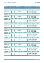
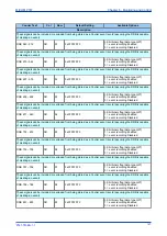
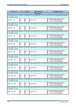
You can control which events cause an event record to be logged in the
RECORD CONTROL
column. The
following table provides details of this control for all event types.
You can view the event records using the settings application software or with the front panel HMI. Select the
event to be viewed on the LCD with the
Select Event
cell in the
VIEW RECORDS
column. A value of '0'
corresponds to the latest event, '1' the next latest and so on. The following subsequent cells display details
about the chosen event. Not all cells are relevant in all cases. The cells displayed depend on the type of
event.
●
Menu Cell Ref
: indicates the event type
●
Time & Date
: indicates the time and date the event occurred
●
Event Text
: displays the event description (2 lines of 16 characters)
●
Event Value
: displays a 32 bit binary number representing the event
●
Evt Iface Source
: displays the interface on which the event was logged
●
Evt Access Level
: records the access level of the interface that initiated the event. This access level
is displayed in this cell.
●
Evt Extra Info
: provides supporting information for the event and can vary between the different event
types.
●
Evt Unique ID
: displays the unique event ID associated with the event.
●
Reset indication
: resets the trip LED indications provided that the relevant protection element has
reset.
2.1
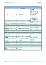
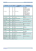
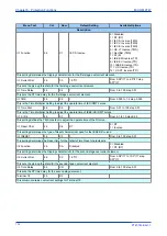
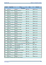
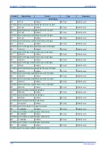
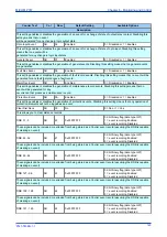
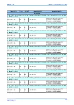
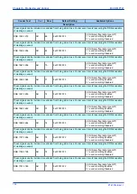
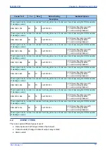
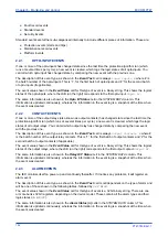
EVENT RECORDS TABLE
Courier Text
Col
Row
Default Setting
Available Options
Description
RECORD CONTROL
0B
00
This column contains settings for Record Controls.
Clear Events
0B
01
No
0= No or 1 = Yes
Clears the events log
Clear Faults
0B
02
No
0= No or 1 = Yes
Clears the fault log
Clear Maint
0B
03
No
0= No or 1 = Yes
Clears the maintenance log
Alarm Event
0B
04
Enabled
0 = Disabled or 1 = Enabled
This setting enables or disables the generation of an event on alarm. Disabling this setting means that no event is
generated for alarms.
Relay O/P Event
0B
05
Enabled
0 = Disabled or 1 = Enabled
Chapter 6 - Monitoring and Control
MiCOM P747
144
P747-TM-EN-1
P747-TM-EN-1.1
Summary of Contents for MiCOM P747 Agile
Page 2: ......
Page 16: ...Contents MiCOM P747 xiv P747 TM EN 1 P747 TM EN 1 1...
Page 20: ...Table of Figures MiCOM P747 xviii P747 TM EN 1 P747 TM EN 1 1...
Page 21: ...INTRODUCTION CHAPTER 1...
Page 22: ...Chapter 1 Introduction MiCOM P747 2 P747 TM EN 1 P747 TM EN 1 1...
Page 31: ...SAFETY INFORMATION CHAPTER 2...
Page 32: ...Chapter 2 Safety Information MiCOM P747 12 P747 TM EN 1 P747 TM EN 1 1...
Page 42: ...Chapter 2 Safety Information MiCOM P747 22 P747 TM EN 1 P747 TM EN 1 1...
Page 43: ...HARDWARE DESIGN CHAPTER 3...
Page 44: ...Chapter 3 Hardware Design MiCOM P747 24 P747 TM EN 1 P747 TM EN 1 1...
Page 74: ...Chapter 3 Hardware Design MiCOM P747 54 P747 TM EN 1 P747 TM EN 1 1...
Page 75: ...CONFIGURATION CHAPTER 4...
Page 76: ...Chapter 4 Configuration MiCOM P747 56 P747 TM EN 1 P747 TM EN 1 1...
Page 117: ...PROTECTION FUNCTIONS CHAPTER 5...
Page 118: ...Chapter 5 Protection Functions MiCOM P747 98 P747 TM EN 1 P747 TM EN 1 1...
Page 160: ...Chapter 5 Protection Functions MiCOM P747 140 P747 TM EN 1 P747 TM EN 1 1...
Page 161: ...MONITORING AND CONTROL CHAPTER 6...
Page 162: ...Chapter 6 Monitoring and Control MiCOM P747 142 P747 TM EN 1 P747 TM EN 1 1...
Page 211: ...SCADA COMMUNICATIONS CHAPTER 7...
Page 212: ...Chapter 7 SCADA Communications MiCOM P747 192 P747 TM EN 1 P747 TM EN 1 1...
Page 259: ...REDUNDANT ETHERNET CHAPTER 8...
Page 260: ...Chapter 8 Redundant Ethernet MiCOM P747 240 P747 TM EN 1 P747 TM EN 1 1...
Page 293: ...CYBER SECURITY CHAPTER 9...
Page 294: ...Chapter 9 Cyber Security MiCOM P747 274 P747 TM EN 1 P747 TM EN 1 1...
Page 313: ...SETTINGS APPLICATION SOFTWARE CHAPTER 10...
Page 314: ...Chapter 10 Settings Application Software MiCOM P747 294 P747 TM EN 1 P747 TM EN 1 1...
Page 322: ...Chapter 10 Settings Application Software MiCOM P747 302 P747 TM EN 1 P747 TM EN 1 1...
Page 323: ...BUSBAR COMMISSIONING TOOL CHAPTER 11...
Page 324: ...Chapter 11 Busbar Commissioning Tool MiCOM P747 304 P747 TM EN 1 P747 TM EN 1 1...
Page 330: ...Chapter 11 Busbar Commissioning Tool MiCOM P747 310 P747 TM EN 1 P747 TM EN 1 1...
Page 331: ...SCHEME LOGIC CHAPTER 12...
Page 332: ...Chapter 12 Scheme Logic MiCOM P747 312 P747 TM EN 1 P747 TM EN 1 1...
Page 348: ...Chapter 12 Scheme Logic MiCOM P747 328 P747 TM EN 1 P747 TM EN 1 1...
Page 349: ...INSTALLATION CHAPTER 13...
Page 350: ...Chapter 13 Installation MiCOM P747 330 P747 TM EN 1 P747 TM EN 1 1...
Page 361: ...COMMISSIONING INSTRUCTIONS CHAPTER 14...
Page 362: ...Chapter 14 Commissioning Instructions MiCOM P747 342 P747 TM EN 1 P747 TM EN 1 1...
Page 387: ...MAINTENANCE AND TROUBLESHOOTING CHAPTER 15...
Page 388: ...Chapter 15 Maintenance and Troubleshooting MiCOM P747 368 P747 TM EN 1 P747 TM EN 1 1...
Page 403: ...TECHNICAL SPECIFICATIONS CHAPTER 16...
Page 404: ...Chapter 16 Technical Specifications MiCOM P747 384 P747 TM EN 1 P747 TM EN 1 1...
Page 425: ...SYMBOLS AND GLOSSARY APPENDIX A...
Page 426: ...Appendix A Symbols and Glossary MiCOM P747 406 P747 TM EN 1 P747 TM EN 1 1...
Page 443: ...COMMISSIONING RECORD APPENDIX B...
Page 444: ...Appendix B Commissioning Record MiCOM P747 424 P747 TM EN 1 P747 TM EN 1 1...
Page 449: ...WIRING DIAGRAMS APPENDIX C...
Page 450: ...Appendix C Wiring Diagrams MiCOM P747 430 P747 TM EN 1 P747 TM EN 1 1...
Page 456: ...Appendix C Wiring Diagrams MiCOM P747 436 P747 TM EN 1 P747 TM EN 1 1...
Page 457: ......

