5
BACKUP OVERCURRENT PROTECTION
Back-up overcurrent protection is disabled by default but can be enabled for additional protection. The
product provides two stages of independent overcurrent protection for each terminal, up to the maximum of
18 terminals. For each terminal, the first stage can be programmed as definite time (DT) or inverse definite
minimum time (IDMT). For IDMT protection, the product provides a choice of curves (IEC, UK, IEEE, and
US). The second stage provides definite time overcurrent protection. In the
CONFIGURATION
column, set
Overcurrent
to
Enabled
. The overcurrent settings then appear in the
GROUP X OVERCURRENT
column
(terminals 1-6), and
GROUP X OVERCURRENT 2
column (terminals 7-18).
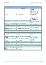
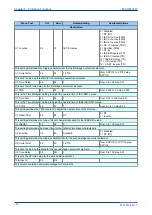
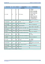
5.1
OVERCURRENT 1 SETTINGS
Menu Text
Col
Row
Default Setting
Available Options
Description
GROUP 1
OVERCURRENT 1
35
00
This column contains settings for Overcurrent
Terminal 1
35
01
This column contains overcurrent settings for Terminal 1
I>1 Function
35
02
IEC S Inverse
0 = Disabled
1 = DT (DT)
2 = IEC S Inverse (TMS)
3 = IEC V Inverse (TMS)
4 = IEC E Inverse (TMS)
5 = UK LT Inverse (TMS)
6 = Rectifier (TMS)
7 = RI (K)
8 = IEEE M Inverse (TD)
9 = IEEE V Inverse (TD)
10 = IEEE E Inverse (TD)
11 = US Inverse (TD)
12 = US ST Inverse (TD)
This setting determines the tripping characteristic for the first stage overcurrent element.
I>1 Current Set
35
04
1.0*I1
From 0.08*I1 to 4.0*I1 step 0.01*I1
This sets the pick-up threshold for the first stage overcurrent element.
I>1 Time Delay
35
05
1
From 0 to 100 step 0.01
This sets the DT time delay for the first stage overcurrent element.
I>1 TMS
35
06
1
From 0.025 to 1.2 step 0.025
This is the Time Multiplier Setting to adjust the operate time of IEC IDMT curves.
I>1 Time Dial
35
07
1
From 0.01 to 100 step 0.01
This is the Time Multiplier Setting to adjust the operate time of IEEE/US IDMT curves.
I>1 K (RI)
35
08
1
From 0.1 to 10 step 0.05
This setting defines the TMS constant to adjust the operate time of the RI curve.
I>1 Reset Char
35
09
DT
0 = DT
1 = Inverse
This setting determines the type of Reset characteristic used for the IEEE/US curves.
I>1 tRESET
35
0A
0
From 0 to 100 step 0.01
This setting determines the Reset time for the Definite Time Reset characteristic.
I>2 Function
35
0B
Disabled
0 = Disabled
1 = DT (DT)
Chapter 5 - Protection Functions
MiCOM P747
116
P747-TM-EN-1
P747-TM-EN-1.1
Summary of Contents for MiCOM P747 Agile
Page 2: ......
Page 16: ...Contents MiCOM P747 xiv P747 TM EN 1 P747 TM EN 1 1...
Page 20: ...Table of Figures MiCOM P747 xviii P747 TM EN 1 P747 TM EN 1 1...
Page 21: ...INTRODUCTION CHAPTER 1...
Page 22: ...Chapter 1 Introduction MiCOM P747 2 P747 TM EN 1 P747 TM EN 1 1...
Page 31: ...SAFETY INFORMATION CHAPTER 2...
Page 32: ...Chapter 2 Safety Information MiCOM P747 12 P747 TM EN 1 P747 TM EN 1 1...
Page 42: ...Chapter 2 Safety Information MiCOM P747 22 P747 TM EN 1 P747 TM EN 1 1...
Page 43: ...HARDWARE DESIGN CHAPTER 3...
Page 44: ...Chapter 3 Hardware Design MiCOM P747 24 P747 TM EN 1 P747 TM EN 1 1...
Page 74: ...Chapter 3 Hardware Design MiCOM P747 54 P747 TM EN 1 P747 TM EN 1 1...
Page 75: ...CONFIGURATION CHAPTER 4...
Page 76: ...Chapter 4 Configuration MiCOM P747 56 P747 TM EN 1 P747 TM EN 1 1...
Page 117: ...PROTECTION FUNCTIONS CHAPTER 5...
Page 118: ...Chapter 5 Protection Functions MiCOM P747 98 P747 TM EN 1 P747 TM EN 1 1...
Page 160: ...Chapter 5 Protection Functions MiCOM P747 140 P747 TM EN 1 P747 TM EN 1 1...
Page 161: ...MONITORING AND CONTROL CHAPTER 6...
Page 162: ...Chapter 6 Monitoring and Control MiCOM P747 142 P747 TM EN 1 P747 TM EN 1 1...
Page 211: ...SCADA COMMUNICATIONS CHAPTER 7...
Page 212: ...Chapter 7 SCADA Communications MiCOM P747 192 P747 TM EN 1 P747 TM EN 1 1...
Page 259: ...REDUNDANT ETHERNET CHAPTER 8...
Page 260: ...Chapter 8 Redundant Ethernet MiCOM P747 240 P747 TM EN 1 P747 TM EN 1 1...
Page 293: ...CYBER SECURITY CHAPTER 9...
Page 294: ...Chapter 9 Cyber Security MiCOM P747 274 P747 TM EN 1 P747 TM EN 1 1...
Page 313: ...SETTINGS APPLICATION SOFTWARE CHAPTER 10...
Page 314: ...Chapter 10 Settings Application Software MiCOM P747 294 P747 TM EN 1 P747 TM EN 1 1...
Page 322: ...Chapter 10 Settings Application Software MiCOM P747 302 P747 TM EN 1 P747 TM EN 1 1...
Page 323: ...BUSBAR COMMISSIONING TOOL CHAPTER 11...
Page 324: ...Chapter 11 Busbar Commissioning Tool MiCOM P747 304 P747 TM EN 1 P747 TM EN 1 1...
Page 330: ...Chapter 11 Busbar Commissioning Tool MiCOM P747 310 P747 TM EN 1 P747 TM EN 1 1...
Page 331: ...SCHEME LOGIC CHAPTER 12...
Page 332: ...Chapter 12 Scheme Logic MiCOM P747 312 P747 TM EN 1 P747 TM EN 1 1...
Page 348: ...Chapter 12 Scheme Logic MiCOM P747 328 P747 TM EN 1 P747 TM EN 1 1...
Page 349: ...INSTALLATION CHAPTER 13...
Page 350: ...Chapter 13 Installation MiCOM P747 330 P747 TM EN 1 P747 TM EN 1 1...
Page 361: ...COMMISSIONING INSTRUCTIONS CHAPTER 14...
Page 362: ...Chapter 14 Commissioning Instructions MiCOM P747 342 P747 TM EN 1 P747 TM EN 1 1...
Page 387: ...MAINTENANCE AND TROUBLESHOOTING CHAPTER 15...
Page 388: ...Chapter 15 Maintenance and Troubleshooting MiCOM P747 368 P747 TM EN 1 P747 TM EN 1 1...
Page 403: ...TECHNICAL SPECIFICATIONS CHAPTER 16...
Page 404: ...Chapter 16 Technical Specifications MiCOM P747 384 P747 TM EN 1 P747 TM EN 1 1...
Page 425: ...SYMBOLS AND GLOSSARY APPENDIX A...
Page 426: ...Appendix A Symbols and Glossary MiCOM P747 406 P747 TM EN 1 P747 TM EN 1 1...
Page 443: ...COMMISSIONING RECORD APPENDIX B...
Page 444: ...Appendix B Commissioning Record MiCOM P747 424 P747 TM EN 1 P747 TM EN 1 1...
Page 449: ...WIRING DIAGRAMS APPENDIX C...
Page 450: ...Appendix C Wiring Diagrams MiCOM P747 430 P747 TM EN 1 P747 TM EN 1 1...
Page 456: ...Appendix C Wiring Diagrams MiCOM P747 436 P747 TM EN 1 P747 TM EN 1 1...
Page 457: ......


