7.3
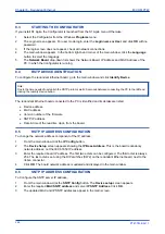
STARTING THE CONFIGURATOR
If you install S1 Agile, the Configurator is launched from the S1 Agile menu. Otherwise:
1.
Select the Configurator from the Windows
Programs
menu.
2.
The Login screen appears. For user mode login, enter the
Login name
as
User
and click
OK
with no
password.
3.
If the login screen does not appear, check all network connections.
4.
The main window appears. In the bottom right-hand corner of the main window, click the
Language
button to select the language.
5.
The
Network Board
drop-down list shows the Network Board, IP Address and MAC Address of the
PC in which the Configurator is running.
7.4
PRP DEVICE IDENTIFICATION
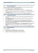
To configure the redundant Ethernet board, go to the main window and click
Identify Device
.
The redundant Ethernet board connected to the PC is identified and its details are listed.
●
Device address
●
MAC address
●
Version number of the firmware
●
SNTP IP address
●
Date & time of the real-time clock, from the board.
7.5
PRP IP ADDRESS CONFIGURATION
To change the network address component of the IP address,
1.
From the main window click the
IP Config
button. The
Device setup
screen appears.
2.
Enter the required board IP address and click
OK
. This is the redundancy network address, not the
IEC 61850 IP address.
3.
The board network address is updated and displayed in the main window.
7.6
SNTP IP ADDRESS CONFIGURATION
To Configure the SNTP server IP address,
1.
From the main window click the
SNTP Config
button. The
Device setup
screen appears.
2.
Enter the required
MAC SNTP address
and server
IP SNTP Address
. Click
OK
.
3.
The updated MAC and IP SNTP addresses appear in the main screen.
7.7
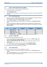
CHECK FOR CONNECTED EQUIPMENT
To check what devices are connected to the device being monitored:
1.
From the main window, select the device.
2.
Click the
Equipment
button.
3.
At the bottom of the main window, a box shows the ports where devices are connected and their MAC
addresses.
MiCOM P747
Chapter 8 - Redundant Ethernet
P747-TM-EN-1
263
P747-TM-EN-1.1
Summary of Contents for MiCOM P747 Agile
Page 2: ......
Page 16: ...Contents MiCOM P747 xiv P747 TM EN 1 P747 TM EN 1 1...
Page 20: ...Table of Figures MiCOM P747 xviii P747 TM EN 1 P747 TM EN 1 1...
Page 21: ...INTRODUCTION CHAPTER 1...
Page 22: ...Chapter 1 Introduction MiCOM P747 2 P747 TM EN 1 P747 TM EN 1 1...
Page 31: ...SAFETY INFORMATION CHAPTER 2...
Page 32: ...Chapter 2 Safety Information MiCOM P747 12 P747 TM EN 1 P747 TM EN 1 1...
Page 42: ...Chapter 2 Safety Information MiCOM P747 22 P747 TM EN 1 P747 TM EN 1 1...
Page 43: ...HARDWARE DESIGN CHAPTER 3...
Page 44: ...Chapter 3 Hardware Design MiCOM P747 24 P747 TM EN 1 P747 TM EN 1 1...
Page 74: ...Chapter 3 Hardware Design MiCOM P747 54 P747 TM EN 1 P747 TM EN 1 1...
Page 75: ...CONFIGURATION CHAPTER 4...
Page 76: ...Chapter 4 Configuration MiCOM P747 56 P747 TM EN 1 P747 TM EN 1 1...
Page 117: ...PROTECTION FUNCTIONS CHAPTER 5...
Page 118: ...Chapter 5 Protection Functions MiCOM P747 98 P747 TM EN 1 P747 TM EN 1 1...
Page 160: ...Chapter 5 Protection Functions MiCOM P747 140 P747 TM EN 1 P747 TM EN 1 1...
Page 161: ...MONITORING AND CONTROL CHAPTER 6...
Page 162: ...Chapter 6 Monitoring and Control MiCOM P747 142 P747 TM EN 1 P747 TM EN 1 1...
Page 211: ...SCADA COMMUNICATIONS CHAPTER 7...
Page 212: ...Chapter 7 SCADA Communications MiCOM P747 192 P747 TM EN 1 P747 TM EN 1 1...
Page 259: ...REDUNDANT ETHERNET CHAPTER 8...
Page 260: ...Chapter 8 Redundant Ethernet MiCOM P747 240 P747 TM EN 1 P747 TM EN 1 1...
Page 293: ...CYBER SECURITY CHAPTER 9...
Page 294: ...Chapter 9 Cyber Security MiCOM P747 274 P747 TM EN 1 P747 TM EN 1 1...
Page 313: ...SETTINGS APPLICATION SOFTWARE CHAPTER 10...
Page 314: ...Chapter 10 Settings Application Software MiCOM P747 294 P747 TM EN 1 P747 TM EN 1 1...
Page 322: ...Chapter 10 Settings Application Software MiCOM P747 302 P747 TM EN 1 P747 TM EN 1 1...
Page 323: ...BUSBAR COMMISSIONING TOOL CHAPTER 11...
Page 324: ...Chapter 11 Busbar Commissioning Tool MiCOM P747 304 P747 TM EN 1 P747 TM EN 1 1...
Page 330: ...Chapter 11 Busbar Commissioning Tool MiCOM P747 310 P747 TM EN 1 P747 TM EN 1 1...
Page 331: ...SCHEME LOGIC CHAPTER 12...
Page 332: ...Chapter 12 Scheme Logic MiCOM P747 312 P747 TM EN 1 P747 TM EN 1 1...
Page 348: ...Chapter 12 Scheme Logic MiCOM P747 328 P747 TM EN 1 P747 TM EN 1 1...
Page 349: ...INSTALLATION CHAPTER 13...
Page 350: ...Chapter 13 Installation MiCOM P747 330 P747 TM EN 1 P747 TM EN 1 1...
Page 361: ...COMMISSIONING INSTRUCTIONS CHAPTER 14...
Page 362: ...Chapter 14 Commissioning Instructions MiCOM P747 342 P747 TM EN 1 P747 TM EN 1 1...
Page 387: ...MAINTENANCE AND TROUBLESHOOTING CHAPTER 15...
Page 388: ...Chapter 15 Maintenance and Troubleshooting MiCOM P747 368 P747 TM EN 1 P747 TM EN 1 1...
Page 403: ...TECHNICAL SPECIFICATIONS CHAPTER 16...
Page 404: ...Chapter 16 Technical Specifications MiCOM P747 384 P747 TM EN 1 P747 TM EN 1 1...
Page 425: ...SYMBOLS AND GLOSSARY APPENDIX A...
Page 426: ...Appendix A Symbols and Glossary MiCOM P747 406 P747 TM EN 1 P747 TM EN 1 1...
Page 443: ...COMMISSIONING RECORD APPENDIX B...
Page 444: ...Appendix B Commissioning Record MiCOM P747 424 P747 TM EN 1 P747 TM EN 1 1...
Page 449: ...WIRING DIAGRAMS APPENDIX C...
Page 450: ...Appendix C Wiring Diagrams MiCOM P747 430 P747 TM EN 1 P747 TM EN 1 1...
Page 456: ...Appendix C Wiring Diagrams MiCOM P747 436 P747 TM EN 1 P747 TM EN 1 1...
Page 457: ......

