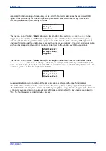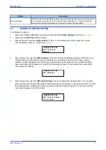
associated function. Locking a function key that is set to the Normal mode causes the associated DDB
signals to be permanently off. This safety feature prevents any inadvertent function key presses from
activating or deactivating critical relay functions.
FUNCTION KEYS
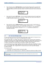
Fn Key 1
Unlocked
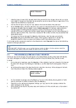
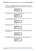
The next cell down (
Fn Key 1 Mode
) allows you to set the function key to
Normal
or
Toggled
. In the
Toggle mode the function key DDB signal output stays in the set state until a reset command is given, by
activating the function key on the next key press. In the Normal mode, the function key DDB signal stays
energised for as long as the function key is pressed then resets automatically. If required, a minimum pulse
width can be programmed by adding a minimum pulse timer to the function key DDB output signal.
FUNCTION KEYS
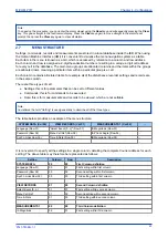
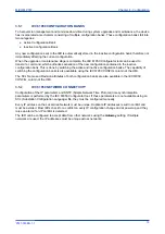
Fn Key 1 Mode
Toggled
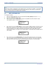
The next cell down (
Fn Key 1 Label
) allows you to change the label of the function. The default label is
Function key 1
in this case. To change the label you need to press the enter key and then change the
text on the bottom line, character by character. This text is displayed when a function key is accessed in the
function key menu, or it can be displayed in the PSL.
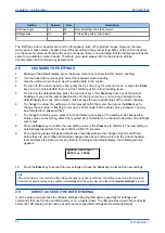
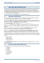
FUNCTION KEYS
Fn Key 1 Label
Function Key 1
Subsequent cells allow you to carry out the same procedure as above for the other function keys.
The status of the function keys is stored in non-volatile memory. If the auxiliary supply is interrupted, the
status of all the function keys is restored. The IED only recognises a single function key press at a time and
a minimum key press duration of approximately 200 ms is required before the key press is recognised in
PSL. This feature avoids accidental double presses.
MiCOM P747
Chapter 4 - Configuration
P747-TM-EN-1
67
P747-TM-EN-1.1
Summary of Contents for MiCOM P747 Agile
Page 2: ......
Page 16: ...Contents MiCOM P747 xiv P747 TM EN 1 P747 TM EN 1 1...
Page 20: ...Table of Figures MiCOM P747 xviii P747 TM EN 1 P747 TM EN 1 1...
Page 21: ...INTRODUCTION CHAPTER 1...
Page 22: ...Chapter 1 Introduction MiCOM P747 2 P747 TM EN 1 P747 TM EN 1 1...
Page 31: ...SAFETY INFORMATION CHAPTER 2...
Page 32: ...Chapter 2 Safety Information MiCOM P747 12 P747 TM EN 1 P747 TM EN 1 1...
Page 42: ...Chapter 2 Safety Information MiCOM P747 22 P747 TM EN 1 P747 TM EN 1 1...
Page 43: ...HARDWARE DESIGN CHAPTER 3...
Page 44: ...Chapter 3 Hardware Design MiCOM P747 24 P747 TM EN 1 P747 TM EN 1 1...
Page 74: ...Chapter 3 Hardware Design MiCOM P747 54 P747 TM EN 1 P747 TM EN 1 1...
Page 75: ...CONFIGURATION CHAPTER 4...
Page 76: ...Chapter 4 Configuration MiCOM P747 56 P747 TM EN 1 P747 TM EN 1 1...
Page 117: ...PROTECTION FUNCTIONS CHAPTER 5...
Page 118: ...Chapter 5 Protection Functions MiCOM P747 98 P747 TM EN 1 P747 TM EN 1 1...
Page 160: ...Chapter 5 Protection Functions MiCOM P747 140 P747 TM EN 1 P747 TM EN 1 1...
Page 161: ...MONITORING AND CONTROL CHAPTER 6...
Page 162: ...Chapter 6 Monitoring and Control MiCOM P747 142 P747 TM EN 1 P747 TM EN 1 1...
Page 211: ...SCADA COMMUNICATIONS CHAPTER 7...
Page 212: ...Chapter 7 SCADA Communications MiCOM P747 192 P747 TM EN 1 P747 TM EN 1 1...
Page 259: ...REDUNDANT ETHERNET CHAPTER 8...
Page 260: ...Chapter 8 Redundant Ethernet MiCOM P747 240 P747 TM EN 1 P747 TM EN 1 1...
Page 293: ...CYBER SECURITY CHAPTER 9...
Page 294: ...Chapter 9 Cyber Security MiCOM P747 274 P747 TM EN 1 P747 TM EN 1 1...
Page 313: ...SETTINGS APPLICATION SOFTWARE CHAPTER 10...
Page 314: ...Chapter 10 Settings Application Software MiCOM P747 294 P747 TM EN 1 P747 TM EN 1 1...
Page 322: ...Chapter 10 Settings Application Software MiCOM P747 302 P747 TM EN 1 P747 TM EN 1 1...
Page 323: ...BUSBAR COMMISSIONING TOOL CHAPTER 11...
Page 324: ...Chapter 11 Busbar Commissioning Tool MiCOM P747 304 P747 TM EN 1 P747 TM EN 1 1...
Page 330: ...Chapter 11 Busbar Commissioning Tool MiCOM P747 310 P747 TM EN 1 P747 TM EN 1 1...
Page 331: ...SCHEME LOGIC CHAPTER 12...
Page 332: ...Chapter 12 Scheme Logic MiCOM P747 312 P747 TM EN 1 P747 TM EN 1 1...
Page 348: ...Chapter 12 Scheme Logic MiCOM P747 328 P747 TM EN 1 P747 TM EN 1 1...
Page 349: ...INSTALLATION CHAPTER 13...
Page 350: ...Chapter 13 Installation MiCOM P747 330 P747 TM EN 1 P747 TM EN 1 1...
Page 361: ...COMMISSIONING INSTRUCTIONS CHAPTER 14...
Page 362: ...Chapter 14 Commissioning Instructions MiCOM P747 342 P747 TM EN 1 P747 TM EN 1 1...
Page 387: ...MAINTENANCE AND TROUBLESHOOTING CHAPTER 15...
Page 388: ...Chapter 15 Maintenance and Troubleshooting MiCOM P747 368 P747 TM EN 1 P747 TM EN 1 1...
Page 403: ...TECHNICAL SPECIFICATIONS CHAPTER 16...
Page 404: ...Chapter 16 Technical Specifications MiCOM P747 384 P747 TM EN 1 P747 TM EN 1 1...
Page 425: ...SYMBOLS AND GLOSSARY APPENDIX A...
Page 426: ...Appendix A Symbols and Glossary MiCOM P747 406 P747 TM EN 1 P747 TM EN 1 1...
Page 443: ...COMMISSIONING RECORD APPENDIX B...
Page 444: ...Appendix B Commissioning Record MiCOM P747 424 P747 TM EN 1 P747 TM EN 1 1...
Page 449: ...WIRING DIAGRAMS APPENDIX C...
Page 450: ...Appendix C Wiring Diagrams MiCOM P747 430 P747 TM EN 1 P747 TM EN 1 1...
Page 456: ...Appendix C Wiring Diagrams MiCOM P747 436 P747 TM EN 1 P747 TM EN 1 1...
Page 457: ......


