background image

GE M

EDICAL

 S

YSTEMS


D

IRECTION

 5184024-100, R

EVISION

 5

LOGIQ

WORKS

 B

ASIC

 S

ERVICE

 M

ANUAL

Chapter 10 Quality Assurance

10-7

10-6-4

Backup and Restore 

(cont’d)

3.) To restore C: drive from the DVD, press “2”. The backup process may take around 30 minutes, and 

then a screen pops up prompting the user to remove the floppy disc and DVD. Follow the 
instructions.

4.) Restart the system. Press “Ctrl+Alt+Del” keys.

10-6-5

Save and Restore 

Following settings are saved by the Save and Restore function: LOGIQworks user and system settings, 
as for example the Hanging Protocols or the Desktop-Window settings, Windows Network and 
Operating System settings as the IP-Address or the Host name. 

Settings and data which cannot be saved by the Save and Restore utility are: DICOM image data and 
Windows specific user settings as for example different users who where created. Normally the 
personal user settings are saved by your computer administrator. Please contact him to be sure not to 
lose any important settings.

10-6-5-1

Save

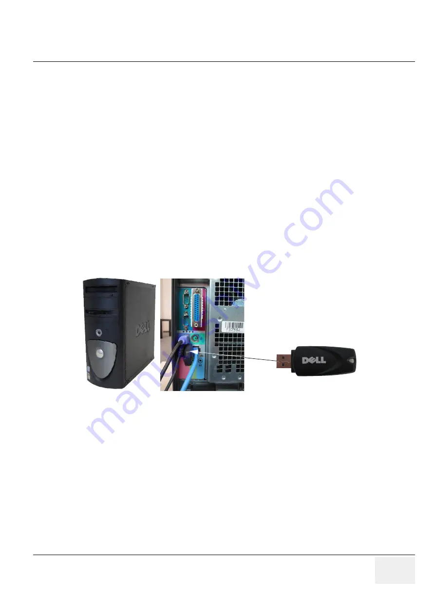
The utility will save all user settings to the USB mass storage device. The USB mass storage device 
must be plugged in and you are requested to enter the assigned drive letter for your USB mass storage 
device (you can find the drive letter by looking in Windows Explorer for “Removable disc”).

1.) Select all contents on the USB mass storage device.

2.) To Save the RA600 settings double-click the ’RA600 settings tool’ icon on the desktop.

3.) Save User and/or System Data.

Figure 10-1  

Summary of Contents for LOGIQworks

Page 1: ...Technical Publication Direction 5184024 100 Revision 5 GE Healthcare LOGIQworks Basic Service Manual Copyright 2002 2007 by General Electric Company Inc All Rights Reserved GE Healthcare...

Page 2: ......

Page 3: ...UE QUE L ANGLAIS IL INCOMBE AU CLIENT DE LE FAIRE TRADUIRE NE PAS TENTER D INTERVENTION SUR LES QUIPEMENTS TANT QUE LE MANUEL DE MAINTENANCE N A PAS T CONSULT ET COMPRIS LE NON RESPECT DE CET AVERTISS...

Page 4: ...PODE P R EM PERIGO A SEGURAN A DO T CNICO OPERADOR OU PACIENTE DEVIDO A CHOQUES EL TRICOS MEC NICOS OU OUTROS IL PRESENTE MANUALE DI MANUTENZIONE DISPONIBILE SOLTANTO IN INGLESE SE UN ADDETTO ALLA MA...

Page 5: ...NYELVEN RHET EL HA A VEV SZOLG LTAT JA ANGOLT L ELT R NYELVRE TART IG NYT AKKOR A VEV FELEL SS GE A FORD T S ELK SZ TTET SE NE PR B LJA ELKEZDENI HASZN LNI A BERENDEZ ST AM G A KARBANTART SI K ZIK NYV...

Page 6: ...VERHOLDELSE AF DENNE ADVARSEL KAN MEDF RE SKADE P GRUND AF ELEKTRISK MEKANISK ELLER ANDEN FARE FOR TEKNIKEREN OPERAT REN ELLER PATIENTEN DEZE ONDERHOUDSHANDLEIDING IS ENKEL IN HET ENGELS VERKRIJGBAAR...

Page 7: ...KANISKE ELLER ANDRE FARER NINIEJSZY PODR CZNIK SERWISOWY DOST PNY JEST JEDYNIE W J ZYKU ANGIELSKIM JE LI FIRMA WIADCZ CA KLIENTOWI US UGI SERWISOWE WYMAGA UDOST PNIENIA PODR CZNIKA W J ZYKU INNYM NI A...

Page 8: ...KNIKER HAR BEHOV AV ETT ANNAT SPR K N ENGELSKA ANSVARAR KUNDEN F R ATT TILLHANDAH LLA VERS TTNINGSTJ NSTER F RS K INTE UTF RA SERVICE P UTRUSTNINGEN OM DU INTE HAR L ST OCH F RST R DEN H R SERVICEHAND...

Page 9: ...GE HEALTHCARE DIRECTION 5184024 100 REVISION 5 LOGIQWORKS BASIC SERVICE MANUAL vii...

Page 10: ...l contractors Other connections between pieces of electrical equipment calibrations and testing shall be performed by qualified GE Healthcare personnel In performing all electrical work on these produ...

Page 11: ...icated in any form in whole or in part without prior written permission of GE Healthcare GE Healthcare may revise this publication from time to time without written notice TRADEMARKS All products and...

Page 12: ...GE HEALTHCARE DIRECTION 5184024 100 REVISION 5 LOGIQWORKS BASIC SERVICE MANUAL x This page was intentionally left blank...

Page 13: ...es Revision Title N A Chapter 3 Installation on page 3 1 to 3 207 5 Chapter 9 Renewal Parts on page 9 1 to 9 10 5 Important Precautions i vi 5 Chapter 4 Functional Checks on page 4 1 to 4 32 5 Chapter...

Page 14: ...GE MEDICAL SYSTEMS DIRECTION 5184024 100 REVISION 5 LOGIQWORKS BASIC SERVICE MANUAL xii This page was intentionally left blank...

Page 15: ...s 1 3 Important Conventions 1 4 Conventions Used in Book 1 4 Standard Hazard Icons 1 5 Product Icons 1 6 Safety Considerations 1 7 Safety Hints 1 7 Label Locations of System based on Dell Precision 3...

Page 16: ...Responsibilities 2 11 Required Features 2 11 Desirable Features 2 11 Patient environment IEC 60601 1 1 2 13 Patient environment IEC 601 1 2 13 Networking Pre installation Requirements 2 14 LOGIQworks...

Page 17: ...36 Double LCD Monitor Installation of System based on Dell Precision 360 or on Dell Precision 370 3 38 Single CRT Monitor Installation 3 42 Double CRT Monitor Installation 3 44 Connections at rear of...

Page 18: ...es 3 99 General Application Level Configuration for LOGIQworks Rev 2 0 and Rev 3 0 3 102 TruAccess Plugin Definition 3 102 General settings 3 104 Logging 3 105 Popup Menu 3 106 System Properties 3 107...

Page 19: ...3 0 3 178 General 3 178 Logging 3 179 Database 3 180 Maintenance 3 181 Viewing Buttons 3 182 Connectivity Application Level 3 183 Setting up and configuring origins 3 183 Setting up and configuring d...

Page 20: ...nnectivity 4 12 Teleradiology 4 12 Configuring Connectivity 4 12 DICOM Properties 4 12 Configuring Destinations 4 12 Configuring Origins 4 14 Setting up an origin 4 14 Receiving Series and Studies 4 1...

Page 21: ...3 Technical Specifications of System based on Dell Precision 370 5 3 Technical Specifications of System based on Dell Precision 380 5 4 Technical Specifications of System based on Dell Precision 390 5...

Page 22: ...hortcuts 5 24 Workstation Directory Tree of LOGIQworks up to Revision 1 3 5 27 Workstation Directory Tree of LOGIQworks 2 0 and 3 0 5 28 Common Service Interface 5 29 Introduction 5 29 iLinq Interacti...

Page 23: ...ll LCD 1901 2001 6 2 Screen Manager 6 2 Screen Adjustment 6 2 Displaying a Low Resolution 6 2 Color Adjustment 6 3 Power save Setup 6 3 Sony Triniton GDM F520 21 CRT 6 4 Monitor On screen Menu Languag...

Page 24: ...emoval 8 3 Monitor Installation 8 5 LCD Monitor Replacement Procedure 8 6 Preparations 8 6 Monitor Removal 8 6 Monitor Installation 8 7 LCD Monitor Replacement Procedure 8 8 Preparations 8 8 Monitor R...

Page 25: ...hapter 9 9 1 List of Abbreviations 9 2 Stock Items 9 2 Non stock Items 9 2 General abbreviations 9 2 LOGIQworks PC versions covered in this manual 9 2 Renewal parts list 9 3 Stock Items FRU 1 and 2 9...

Page 26: ...Requirements for Periodic Maintenance 10 4 Safety Inspections 10 5 Electrical Safety Tests 10 5 Specifications to meet 10 5 PC Maintenance 10 6 LOGIQworks units Outer casing 10 6 Monitor Screen 10 6 K...

Page 27: ...ter 4 Functional Checks Contains functional checks that must be performed as part of the installation or as required during servicing and periodic maintenance 5 Chapter 5 Components and Functions Theo...

Page 28: ...1 2 LOGIQworks Standard Hardware of System based on Dell Precision 340 delivered from April 2003 to April 2004 Table 1 3 LOGIQworks Standard Hardware of System based on Dell Precision 360 delivered si...

Page 29: ...ter 3 Section 3 4 4 on page 3 60 1 1 4 2 How to Check for Hardware Software version Options See chapter 3 Section 3 5 13 on page 3 203 1 1 5 Purpose of Operator Manual s The Operator Manual s Part Num...

Page 30: ...n the product and in the service information are described in this chapter Safety Precaution Messages Various levels of safety precaution messages may be found on the equipment and in the service info...

Page 31: ...ition to text several different graphical icons symbols may be used to make you aware of specific types of hazards that could cause harm Other hazard icons make you aware of specific procedures that s...

Page 32: ...Class Label Used to indicate the degree of safety or protection CAUTION This unit weighs Special care must be used to avoid This precaution is intended to prevent injury that may result if one person...

Page 33: ...ns Supply ON OFF switches Mains ON Indicates the power on position of the mains power switch Protective Earth Indicates the protective earth grounding terminal Equipotentiality Indicates the terminal...

Page 34: ...l a galvanic isolator to insulate the connection between the personal computer and all connected medical equipment e g fibre optic cable or certified video isolator Set up the personal computer outsid...

Page 35: ...your service representative WARNING WARNING Danger of Data Loss System connected to the inter intranet could be infected by a computer virus This infection can result in a loss of data or falsified d...

Page 36: ...RVICE MANUAL 1 10 Section 1 3 Safety Considerations 1 3 2 Label Locations of System based on Dell Precision 340 Sony Labels only Guarantee agreement 1 CE Label 2 VDE Label 3 UL Label 4 Identification...

Page 37: ...5 LOGIQWORKS BASIC SERVICE MANUAL Chapter 1 Introduction 1 11 1 3 2 Label Locations of System based on Dell Precision 340 cont d Figure 1 3 Computer Tower Labelling Power Input Information Tower Rear...

Page 38: ...C SERVICE MANUAL 1 12 Section 1 3 Safety Considerations 1 3 2 Label Locations of System based on Dell Precision 340 cont d Figure 1 4 CRT Monitor Labels Figure 1 5 LCD NEC 1880 Monitor Labels Serial N...

Page 39: ...0 REVISION 5 LOGIQWORKS BASIC SERVICE MANUAL Chapter 1 Introduction 1 13 1 3 2 Label Locations of System based on Dell Precision 340 cont d Figure 1 6 Recovery CD Label with Rating Plate Label Figure...

Page 40: ...BASIC SERVICE MANUAL 1 14 Section 1 3 Safety Considerations 1 3 3 Label Locations of System based on Dell Precision 360 and Dell Precision 370 Figure 1 8 Computer Tower Labeling Power Input Informatio...

Page 41: ...REVISION 5 LOGIQWORKS BASIC SERVICE MANUAL Chapter 1 Introduction 1 15 1 3 3 Label Locations of System based on Dell Precision 360 and Dell Precision 370 cont d Tower Front Figure 1 9 Additional Compu...

Page 42: ...ANUAL 1 16 Section 1 3 Safety Considerations 1 3 3 Label Locations of System based on Dell Precision 360 and Dell Precision 370 cont d Figure 1 11 LCD DELL 1901 Monitor Labels Figure 1 10 LCD DELL 200...

Page 43: ...VISION 5 LOGIQWORKS BASIC SERVICE MANUAL Chapter 1 Introduction 1 17 1 3 4 Label Locations of System based on Dell Precision 380 and Dell Precision 390 Figure 1 13 Figure 1 12 Computer Tower Labeling...

Page 44: ...ECTION 5184024 100 REVISION 5 LOGIQWORKS BASIC SERVICE MANUAL 1 18 Section 1 3 Safety Considerations 1 3 5 Label Locations Figure 1 14 Recovery CD Label with Rating Plate Label Figure 1 15 Modem Label...

Page 45: ...ssistance Location Phone Number USA Canada GE Medical Systems Ultrasound Service Engineering 4855 W Electric Avenue Milwaukee WI 53219 Customer Answer Center Service 1 800 437 1171 1 800 321 7937 Lati...

Page 46: ...WORKS BASIC SERVICE MANUAL 1 20 Section 1 4 Customer Assistance 1 4 2 System Manufacturer Table 1 10 Phone Numbers for Customer Assistance Manufacturer Phone Number ViewPoint Bildverarbeitung GmbH Arg...

Page 47: ...e installation of a LOGIQworks Included are descriptions of the facility and electrical needs to be met by the purchaser of the unit A checklist is also provided at the end of this section to help det...

Page 48: ...300 BTU hr Demand on the cooling system Operation Non Operation Storage Transport Temperature 10 to 35 oC 50 to 95 o F 40 to 65 oC 40 to 149o F 40 to 65 oC 40 to 149o F 40 to 65 oC 40 to 149 o F Humi...

Page 49: ...atient comfort may be optimized if the room light is subdued and indirect Therefore a combination lighting system dim bright is recommended Keep in mind that lighting controls and dimmers can be a sou...

Page 50: ...300 BTU hr Demand on the cooling system Table 2 6 Dell Precision 360 Dell Precision 370 Dell Precision 380 Dell Precision 390 Workstation Operation Storage Transport Temperature 10 to 35 oC 50 to 95...

Page 51: ...LCD1 LCD2 Modem BTU h 860 195 195 164 Power W 250 57 57 48 Total BTU h LOGIQworks Models H49021AC x x x 1220 H49021AD x x x x 1415 H49021AA x x x 1220 H49021AB x x x x 1415 Table 2 10 LOGIQworks Stand...

Page 52: ...a source of EMI which could degrade image quality These controls should be selected to minimize possible interference 2 2 3 Time and Manpower Requirements Site preparation takes time Begin Pre instal...

Page 53: ...tribution panel before the system The dedicated line shall consist of one phase a neutral not shared with any other circuit and a full size ground wire from the distribution panel to the workstation P...

Page 54: ...Plug If the unit arrives without a power plug or with the wrong plug you must contact GE Service they must supply what is locally required WARNING WARNING POWER OUTAGE MAY OCCUR The LOGIQworks require...

Page 55: ...terference see Table 2 16 for EMI Prevention tips WARNING WARNING Danger of Electromagnetic Incompatibility Devices that are not CE marked can create an electromagnetic field which could impair the op...

Page 56: ...SION 5 LOGIQWORKS BASIC SERVICE MANUAL 2 10 Section 2 2 General Console Requirements Take care with cellular phones Cellular phones may transmit a 5 V m signal that could cause image artifacts Table 2...

Page 57: ...y 2 3 2 Required Features Dedicated single branch power outlets of adequate amperage see Table 2 14 meeting all local and national codes which is located less than 1 5 m 5 ft from the workstation s pr...

Page 58: ...Ultrasound Scanner 3 to 4 dedicated Power outlets Vivid 3 A dedicated Ethernet network wall outlet Work Station parts A dedicated Analog Telephone jack 1m14cm 304 8 cm 243 84 cm A dedicated Power out...

Page 59: ...nvironment IEC 601 1 Sub clause 2 204 Such an area is an environment in which medical diagnosis monitoring or treatment is carried out It is very difficult to attach unique dimensions to the PATIENT E...

Page 60: ...age 14 Ensure that there are no spaces in any field of the form except for those fields under PHYSICAL LOCATION Entries must include Verify that there is a Conformancy Statement that documents the DIC...

Page 61: ...GE MEDICAL SYSTEMS DIRECTION 5184024 100 REVISION 5 LOGIQWORKS BASIC SERVICE MANUAL Chapter 2 Pre Installation 2 15 2 3 4 4 Insite 2 cont d Figure 2 4 Data Collection Document Page 1...

Page 62: ...GE MEDICAL SYSTEMS DIRECTION 5184024 100 REVISION 5 LOGIQWORKS BASIC SERVICE MANUAL 2 16 Section 2 3 Facility Needs 2 3 4 4 Insite 2 cont d Figure 2 5 Data Collection Document Page 2...

Page 63: ...GE MEDICAL SYSTEMS DIRECTION 5184024 100 REVISION 5 LOGIQWORKS BASIC SERVICE MANUAL Chapter 2 Pre Installation 2 17 2 3 4 4 Insite 2 cont d Figure 2 6 Data Collection Document Page 3...

Page 64: ...GE MEDICAL SYSTEMS DIRECTION 5184024 100 REVISION 5 LOGIQWORKS BASIC SERVICE MANUAL 2 18 Section 2 3 Facility Needs 2 3 4 4 Insite 2 cont d Figure 2 7 Data Collection Document Page 4...

Page 65: ...GE MEDICAL SYSTEMS DIRECTION 5184024 100 REVISION 5 LOGIQWORKS BASIC SERVICE MANUAL Chapter 2 Pre Installation 2 19 2 3 4 4 Insite 2 cont d Figure 2 8 Data Collection Document Page 5...

Page 66: ...GE MEDICAL SYSTEMS DIRECTION 5184024 100 REVISION 5 LOGIQWORKS BASIC SERVICE MANUAL 2 20 Section 2 3 Facility Needs Your Notes...

Page 67: ...re the facility and unit of the actual installation and how to check and test the unit and external peripherals for electrical safety are included in this procedure 3 1 2 Average Installation Time For...

Page 68: ...very cold or hot do not turn on its power until it has had a chance to acclimate to its operating environment Table 3 2 LOGIQworks Acclimate Time C 40 35 30 25 20 15 10 5 0 5 10 15 20 25 30 35 40 45...

Page 69: ...4 Open each of these cardboard boxes 5 Check that contents are there and undamaged 6 Move the shipment to the place where it is to be installed 7 Unpack the Parts run the check list shown below 8 Han...

Page 70: ...considerable distances or on an incline by one person could result in injury or damage or both Figure 3 1 Shipping packaging and envelope at front panel of the crate CAUTION The device must only be t...

Page 71: ...GIQWORKS BASIC SERVICE MANUAL Chapter 3 Installation 3 5 3 2 1 1Check of Delivered Box cont d Table 3 3 The LOGIQworks H49021LC parts Figure 3 2 The LOGIQworks H49021LC delivery Name Qty 1 Dell Precis...

Page 72: ...C SERVICE MANUAL 3 6 Section 3 2 Receiving and Unpacking the Equipment 3 2 1 1Check of Delivered Box cont d Table 3 4 The LOGIQworks H49021LD parts Figure 3 3 The LOGIQworks H49021LD delivery Name Qty...

Page 73: ...IQWORKS BASIC SERVICE MANUAL Chapter 3 Installation 3 7 3 2 1 1Check of Delivered Box cont d Table 3 5 The LOGIQworks H49021LA parts Figure 3 4 The LOGIQworks H49021LA delivery Item Name Qty 1 Dell Pr...

Page 74: ...IC SERVICE MANUAL 3 8 Section 3 2 Receiving and Unpacking the Equipment 3 2 1 1Check of Delivered Box cont d Table 3 6 The LOGIQworks H49021LB parts Figure 3 5 The LOGIQworks H49021LB delivery Name Qt...

Page 75: ...1AA or H49021AK H49021AM delivery Table 3 7 The LOGIQworks 1FP H49021AA H49021AC parts Name Qty 1 Dell Precision 360 or Dell Precision 370 1 2 Monitor Dell LCD 1901 Europe 1 3 Monitor Dell LCD 2001 US...

Page 76: ...rks H49021AD H49021AB or H49021AL H49021AN delivery Table 3 9 The LOGIQworks H49021AD H49021AB parts Name Qty 1 Dell Precision 360 or Dell Precision 370 1 or 1 2 Monitor Dell LCD 1901 Europe 2 Monitor...

Page 77: ...ion 340 Table 3 11 Contents of CPU Box of System based on Dell Precision 340 Figure 3 8 Contents of CPU Box Item Name Qty 1 Dell Precision 340 1 2 US Keyboard 1 3 Installation Guide Setup 1 4 Quick Re...

Page 78: ...ion 370 Figure 3 9 Contents of CPU Box of System based on Dell Precision 360 or on Dell Precision 370 Table 3 12 Contents of CPU Box of System based on Dell Precision 360 or on Dell Precision 370 Item...

Page 79: ...ontents of CPU Box of System based on Dell Precision 380 and Dell Precision 390 Table 3 13 Contents of CPU Box of System based on Dell Precision 380 and Dell Precision 390 Item Name Qty 1 Dell Precisi...

Page 80: ...x of System based on Dell Precision 340 Table 3 14 CPU Box parts list Figure 3 11 Additional Parts in CPU Box Item Name Qty 1 Basic Service Manual 1 2 Quick Guide with User Manual CD 1 3 Quick Card 1...

Page 81: ...ion 390 Figure 3 12 Additional Parts in CPU Box of System based on Dell Precision 360 Dell Precision 370 Dell Precision 380 and Dell Precision 390 Table 3 15 CPU Box parts list Item Name Qty 1 Quick C...

Page 82: ...SIC SERVICE MANUAL 3 16 Section 3 2 Receiving and Unpacking the Equipment 9 Optical USB Mouse 1 10 Software Option Dongle 1 11 USB Harddisk 3 5 13 Instant CD DVD 15 Powercord FP2001US for US only 1 2...

Page 83: ...n Dell Precision 340 Table 3 16 Contents of LCD Monitor Figure 3 13 Parts in the LCD delivery of System based on Dell Precision 340 Item Name Qty 1 Monitor LCD 1 2 Signal Cable analog 1 3 Signal Cable...

Page 84: ...Precision 390 Figure 3 14 Parts in the LCD delivery of System based on Dell Precision 360 Dell Precision 370 Dell Precision 380 or Dell Precision 390 Table 3 17 Contents of LCD monitor of System based...

Page 85: ...2 1 5 Sony CRT Monitor Table 3 18 Contents of CRT Monitor Box Figure 3 15 Parts in the CRT delivery Item Name Qty 1 Monitor CRT 1 2 Signal Cable analog 1 3 Power Cable EU 1 4 Documentation 1 If not s...

Page 86: ...Part Number Qty 1 Read Me First Document Part of GE Part Number 2245794 1 2 Modem GE Part Number 2245794 1 3 Telephone cable Part of GE Part Number 2245794 1 4 Telephone Wire Part of GE PartNumber 22...

Page 87: ...and Dell Precision 390 Table 3 20 Modem Parts Table Figure 3 17 Modem Parts overview ITE M Name Part Number Qty 1 Installation CD Part of GE Part Number 2413338 1 2 Modem GE Part Number 2413338 1 3 T...

Page 88: ...Settings Verify that the LOGIQworks has the correct voltage delivery Figure 3 18 Correct Voltage Settings Table 3 21 International Voltage and Frequencies settings Country V Hz Argentina 220 50 Austr...

Page 89: ...0 Italy 230 50 Japan 100 50 60 Korea South 220 60 Luxembourg 220 50 Mexico 127 60 Monaco 127 220 50 Netherlands 230 50 New Zealand 230 50 Norway 230 50 Poland 230 50 Portugal 220 50 Russian Federation...

Page 90: ...for DELL PC and DELL Monitor FP1901 Multitech Modem Name Part Number Power Cord US 2369732 Power Cord French 2369733 Power Cord German 2369734 Power Cord Italian 2369735 Power Cord Spanish 2369736 WAR...

Page 91: ...Depth Unit DellPrecision 340 42 5 18 1 44 7 cm 17 0 7 1 17 5 Inches Sony GDM F520 49 9 49 7 48 7 cm 19 0 19 4 19 0 Inches NEC LCD 1880 39 4 38 7 18 0 cm 15 0 15 1 7 0 Inches Modem 10 9 2 5 14 5 cm 4...

Page 92: ...Installation 3 4 1 2 Required Space for LOGIQworks Installation Figure 3 19 Required Space for System with 1 CRT Monitor Figure 3 20 Required Space for System with 2 CRT Monitors min 100 min 80cm rec...

Page 93: ...7 3 4 1 2 Required Space for LOGIQworks Installation cont d Figure 3 21 Required Space for System with 1 LCD Monitor Figure 3 22 Required Space for System with 2 LCD Monitors min 80 min 80cm recommend...

Page 94: ...al Specifications To see the Electrical Specifications for the LOGIQworks see Table 2 14 on page 2 7 Power Consumption nominal 550 VA including all options Model Weight kg Weight lbs Dell Precision 34...

Page 95: ...1 Place the Parts ergonomically correct 1 Place the Monitor Keyboard Mouse Peripherals Desk and stool ergonomically correct and place the Tower Computer either on the floor below the desk or on the d...

Page 96: ...ERVICE MANUAL 3 30 Section 3 4 Completing the Installation 3 4 3 2 Single LCD Monitor Installation of System based on Dell Precision 340 Items needed Figure 3 24 Items needed for Single LCD Monitor In...

Page 97: ...ll Precision 340 cont d Table 3 28 Items needed for Single LCD Monitor Installation Item Name Qty 1 Dell Precision 340 1 2 Monitor NEC LCD 1880 Sx 1 3 Signal Cable digital 1 4 Y Monitor Cable digital...

Page 98: ...3 4 Completing the Installation 3 4 3 3 Single LCD Monitor Installation of System based on Dell Precision 360 or on Dell Precision 370 Items needed Figure 3 25 Items needed for Single LCD Monitor Ins...

Page 99: ...d Table 3 29 Items needed for Single LCD Monitor Installation Item Name Qty 1 Dell Precision 360 or Dell Precision 370 1 2 Monitor Dell LCD 1901 or LDCD 2001 1 3 Signal Cable digital 1 4 Cat5 Patch c...

Page 100: ...on 3 4 Completing the Installation 3 4 3 4 Single LCD Monitor Installation of System based on Dell Precision 380 and Dell Precision 390 Items needed Figure 3 26 Items needed for Single LCD Monitor Ins...

Page 101: ...Items needed for Single LCD Monitor Installation Item Name Qty 1 Dell Precision 380 Dell Precision 390 1 2 Monitor Dell LCD 1901 or LDCD 2001 1 3 Signal Cable digital 1 4 Cat5 Patch cable 1 5 Keyboard...

Page 102: ...BASIC SERVICE MANUAL 3 36 Section 3 4 Completing the Installation 3 4 3 5 Double LCD Monitor Installation of System based on Dell Precision 340 Figure 3 27 Items needed for Double LCD Monitor Installa...

Page 103: ...ed on Dell Precision 340 cont d Table 3 31 Double LCD Monitor Installation Item Name Qty 1 Dell Precision 340 1 2 Monitor NEC LCD 1880 Sx 2 3 Signal Cable digital 2 4 Y Monitor Cable digital 1 5 Cat5...

Page 104: ...Section 3 4 Completing the Installation 3 4 3 6 Double LCD Monitor Installation of System based on Dell Precision 360 or on Dell Precision 370 Figure 3 28 Items needed for Double LCD Monitor Installa...

Page 105: ...d Table 3 32 Items needed for Double LCD Monitor Installation Item Name Qty 1 Dell Precision 360 or Dell Precision 370 1 2 Monitor Dell LCD 1901 or LCD 2001 2 3 Signal Cable digital 2 4 Cat5 Patch ca...

Page 106: ...Section 3 4 Completing the Installation Table 3 33 Double LCD Monitor Installation of System based on Dell Precision 380 and Dell Precision 390 Figure 3 29 Items needed for Double LCD Monitor Installa...

Page 107: ...370 cont d Table 3 34 Items needed for Double LCD Monitor Installation Item Name Qty 1 Dell Precision 380 Dell Precision 390 1 2 Monitor Dell LCD 1901 or LCD 2001 2 3 Signal Cable digital 2 4 Cat5 Pa...

Page 108: ...ECTION 5184024 100 REVISION 5 LOGIQWORKS BASIC SERVICE MANUAL 3 42 Section 3 4 Completing the Installation 3 4 3 7 Single CRT Monitor Installation Figure 3 30 Items for Single CRT Monitor Installation...

Page 109: ...Table 3 35 Items for Single CRT Monitor Installation Item Name Qty 1 Dell Precision 380 Dell Precision 390 1 2 Monitor Sony GDM F520 1 3 Signal Cable analog 1 4 Y Monitor Cable analog 1 5 Cat5 Patch...

Page 110: ...4024 100 REVISION 5 LOGIQWORKS BASIC SERVICE MANUAL 3 44 Section 3 4 Completing the Installation 3 4 3 8 Double CRT Monitor Installation Items needed Figure 3 31 Items needed for Double CRT Monitor In...

Page 111: ...Precision 340 1 2365947 2 Monitor Sony GDM F520 2 2365798 3 Signal Cable analog 2 2368273 4 Y Monitor Cable analog 1 2368269 5 Cat5 Patch cable 1 2366640 6 RA600 Dongle 1 see Centricity RA600 Service...

Page 112: ...4 Completing the Installation 3 4 3 9 Connections at rear of PC of System based on Dell Precision 340 Figure 3 32 Connections at rear of PC of System based on Dell Precision 340 Y Monitor Cable DVD IE...

Page 113: ...ect the USB Harddisk to the other USB Connector 3 Connect the USB Software Option Dongle 4 Connect the parallel RA600 Dongle 3 4 3 11 Keyboard and Network Connection of Dell Precision 360 1 Connect PS...

Page 114: ...MS DIRECTION 5184024 100 REVISION 5 LOGIQWORKS BASIC SERVICE MANUAL 3 48 Section 3 4 Completing the Installation 3 4 3 11 Keyboard and Network Connection of Dell Precision 360 cont d Figure 3 34 Keybo...

Page 115: ...184024 100 REVISION 5 LOGIQWORKS BASIC SERVICE MANUAL Chapter 3 Installation 3 49 3 4 3 12 Connections at Rear of PC of System based on Dell Precision 370 Figure 3 35 Connections at rear of PC of Syst...

Page 116: ...nitor 2 Connect the other end to a Wall Power Outlet 3 Connect the Y Monitor Signal Cable to the display Card Socket at the rear of the PC 4 Connect the Monitor Signal Cable to the Y Monitor Cable tag...

Page 117: ...YSTEMS DIRECTION 5184024 100 REVISION 5 LOGIQWORKS BASIC SERVICE MANUAL Chapter 3 Installation 3 51 3 4 3 13 Monitor Connections of System based on Dell Precision 340 cont d Figure 3 37 PC and LCD Rea...

Page 118: ...end to a Wall Power Outlet 3 Connect the Y Monitor Signal Cable to the display Card Socket at the rear of the PC 4 Connect the Monitor Signal Cable to the Y Monitor Cable tagged with 1 5 Connect the...

Page 119: ...CE MANUAL Chapter 3 Installation 3 53 3 4 3 15 Monitor Connections of System based on Dell Precision 360 1 Connect the Monitor Power Cable to the rear of the Monitor 2 Connect the other end to a Wall...

Page 120: ...ions of System based on Dell Precision 360 cont d 3 Connect the Y Monitor Signal Cable to the display Card Socket at the rear of the PC 4 Connect the other end to the digital Monitor Signal input1 as...

Page 121: ...itor Power Cable to the rear of the Monitor 2 Connect the other end to a Wall Power Outlet 3 Connect the Y Monitor Signal Cable to the display Card Socket at the rear of the PC 4 Connect the Monitor S...

Page 122: ...BASIC SERVICE MANUAL 3 56 Section 3 4 Completing the Installation 3 4 3 16 Monitor Connections of System based on Dell Precision 370 cont d 6 In case of dual Monitor installation connect the second Mo...

Page 123: ...ASIC SERVICE MANUAL Chapter 3 Installation 3 57 3 4 3 17 PC Connections 1 Connect the female end of the PC Power Cable to the Power Socket on the PC and the other end to a wall Power Outlet Figure 3 4...

Page 124: ...vertor and the male end into a vacant AC power outlet on the wall b Plug the AC DC convertor cable into the PWR jack on the modem Figure 3 45 Global Modem Signal and Power connections for Dell Precisi...

Page 125: ...0 REVISION 5 LOGIQWORKS BASIC SERVICE MANUAL Chapter 3 Installation 3 59 3 4 3 18 Global Modem Connections cont d Figure 3 46 Global Modem Signal Connection for Dell Precision 360 Dell Precision 370 D...

Page 126: ...Power On Boot Up Table 3 37 Bootup Step Check Expected Result 1 Turn ON the Power switch Drag down the menu 2 Administrator Admin Password should be changed after first use On the appearing dialog ty...

Page 127: ...IC SERVICE MANUAL Chapter 3 Installation 3 61 3 4 5 Third Party Products The third party product Nero Burning ROM needs to be installed from the vendor setup CDs Please use the default installation se...

Page 128: ...pare first the client customer PC After the client PC is prepared you or somebody in the OLC can finish the checkout using the VOLC software To prepare the client PC you should know the GE InSite IP a...

Page 129: ...as device connection type 7 Select one of the following items corresponding to your telephone connection Dial out prefix Internal prefix COM3 serial port Dialing Mode Modem Type MultiTech MT5634 ZBA...

Page 130: ...on cont d 11 The Phone and Modem Options window pops up Click on Remove and then Add 12 Follow the instructions of the Add Remove Hardware Wizard 13 Click Next to start the installation process Wait u...

Page 131: ...OK 15 Click on the InSite Checkout tab 16 Enter the correct GE InSite IP address 17 Click Checkout now and reboot the system The PC is ready for OLC checkout now 3 4 6 2 VPN Configuration 1 Open the...

Page 132: ...ng the Installation 3 4 6 2 VPN Configuration cont d 2 Select network on the Device Connection Type field 3 Enter the local gateway IP address 4 Click Apply 5 Select the InSite Checkout tab 6 Click Ch...

Page 133: ...for LOGIQworks 3 0 For Installation Inside II see Technical Publication Installation Manual InSite II ViewPoint LOGIQworks Direction 5181936 100 3 4 8 Filling out and sending the Product Locator Card...

Page 134: ...u provided with the Data Collection Document please refer to Section Recommendation A permanent broadband to the internet The customer is responsible for the connectivity configuration and operation o...

Page 135: ...IC SERVICE MANUAL Chapter 3 Installation 3 69 3 5 1 1 Set System Time cont d 4 Click on OK 5 Select the Date Time tab and set the time and date appropriately 6 Click OK to apply the changes Figure 3 5...

Page 136: ...click Regional Options in the Windows Control Panel Click the Numbers tab and select U S or Metric from the Measurement System drop down list Then click OK If you wish to overrule Windows Regional Se...

Page 137: ...he Display Properties page opens 3 Select the Settings tab and click Advanced Set up your system for single monitor use On the ATI Displays Tab only one monitor is available You don t need to apply an...

Page 138: ...figuration 3 5 1 3 1 Monitor Setup based on Dell 340 Set up your system for dual monitor use 4 On the ATI Displays Tab make sure that both monitors are checked and activated green light shows activati...

Page 139: ...button for the left monitor For the right monitor select the to create an extended desktop to the right Do not use the clone button 6 The resolution for both monitors shall be identical for both moni...

Page 140: ...VICE MANUAL 3 74 Section 3 5 Configuration 3 5 1 3 2 Set up your system for true dual graphic card use based on Dell 360 Figure 3 62 Dual Monitor Configuration for True Dual Graphic Card Figure 3 63 D...

Page 141: ...GE MEDICAL SYSTEMS DIRECTION 5184024 100 REVISION 5 LOGIQWORKS BASIC SERVICE MANUAL Chapter 3 Installation 3 75 3 5 1 3 Monitor Setup cont d Figure 3 64 Dual Monitor connection for Dell Precision 370...

Page 142: ...lease refer to Section 3 5 4 6 Receive on page 3 140 for details on how to configure the receive behavior of LOGIQworks through the Connection Service Also please refer to Section 3 5 10 Connectivity...

Page 143: ...you will receive a non US keyboard All keyboard input locales will be pre configured Please check whether settings are correct 1 Click on the keyboard setup button the following window will appear NO...

Page 144: ...t d 2 Click on Input Locals the following window will appear 3 Use the scroll bar to find the correct language keyboard layout for your keyboard 4 Click on the Set as Default button 5 Click on Apply b...

Page 145: ...2 If TruAccess Raw Data Processing is not yet listed in the Installed Plugins window click Add to open the Add Plugin Definitions dialog box If it is already listed quit the dialog by clicking on Canc...

Page 146: ...5 LOGIQWORKS BASIC SERVICE MANUAL 3 80 Section 3 5 Configuration 3 5 2 1 TruAccess Plugin Definition cont d Resulting list of installed plugins after TruAccess Raw Data Processing has been added Figu...

Page 147: ...OOT Directory Root directory of RA 600 This is the directory into which RA 600 has been installed Default C AMI_61 Work Directory Directory for temporary files created by RA 600 Default D AMI_61 WORK...

Page 148: ...LOGIQworks will collapse all the studies into one folder for viewing on the Local Patient Worklist provided that the studies have the same patient name and or patient ID Default Both name and ID 3 5...

Page 149: ...troubleshooting Log File Set the name of the general log file Each Service has its own default log filename See the Database Service Connection Service and Print Service properties for details Default...

Page 150: ...es next to the menu items to select the ones you want to appear on the pop up menu that appears when right clicking in the Data Selector 3 5 2 5 System Properties To set display system properties 1 Se...

Page 151: ...see Figure 3 74 LOGIQworks will use the settings as specified in Regional Settings in the Windows Control Panel see Section 3 5 1 2 on page 3 70 Default METRIC If you wish to overrule Windows regional...

Page 152: ...s by means of double byte character sets typical for displaying far eastern languages such as Japanese Chinese and Korean Phonetic also displays patient names using double byte character sets but show...

Page 153: ...provided by your system The AE Title entered here should be used by other systems to set up DICOM associations to your system The same AE Title is also used by your system when it sets up association...

Page 154: ...Selector menu and click the monitor tab 2 Select the Adapter and click Settings Specify that 1 row and 1 column of monitors 1x1 are connected to that adapter 3 Select the Monitor Group and click Edit...

Page 155: ...the Adapter and click Settings Specify that 1 row and 2 columns of monitors 1 x 2 are connected to that adapter 3 Select the Monitor Group and click Edit Specify that 1 row and 2 columns of monitors 1...

Page 156: ...lector menu and click the monitor tab 2 Select the Adapter and click Settings Specify that 1 row and 1 column of monitors 1x1 are connected to that adapter 3 Select the Monitor Group and click Edit Sp...

Page 157: ...3 Installation 3 91 3 5 2 8 Monitors of System Dell Precision 360 and of Dell Precision 370 cont d Setting up LOGIQworks for use with dual monitors for true dual graphic card log on as system administ...

Page 158: ...r tab 2 Select the Adapter and click Settings Specify that 1 row and 1 columns of monitors 1 x 1 are connected to that adapter 3 Select the Monitor Group and click Edit Specify that 1 row and 2 column...

Page 159: ...r to be saved with the study in the Save Data dialog drop down list in the Viewing Section see Section 3 5 2 12 on page 3 99 in the Configuration Menu The priority of the statuses is from low to high...

Page 160: ...figuration 3 5 2 9 Study Statuses cont d The backslash separates the DICOM description with your own description of that particular status For this you may use more than one word separated by spaces F...

Page 161: ...d be present while doing so Once all the status permissions have been configured the System Administrator should uncheck the Allow other users to configure their status permissions check box by loggin...

Page 162: ...select The user can be allowed to set the status back to a lower one from Authorized to Created for example In some cases however this may cause workflow problems Check the Allow user to set back the...

Page 163: ...s own DLL which allows you to work with Local Database and DICOM Modality Work lists Implementations During installation of LOGIQworks a default implementation will be installed Click the Add button t...

Page 164: ...Worklist which will be retrieved from the HIS RIS and shown in the Data Selector Report The HIS RIS which will send report information whether a report should be written or if the study has already b...

Page 165: ...hapter 3 Installation 3 99 3 5 2 12 Viewing Properties To set general viewing properties 1 Select Configuration Viewing from the Data Selector menu 2 Select the General tab from the Viewing Properties...

Page 166: ...is check box if you want LOGIQworks to display in the Viewing Section a menu bar with commands for viewing images Data Direct View LOGIQworks can allow studies that are not immediately available on th...

Page 167: ...101 3 5 2 12 Viewing Properties cont d Open Priors for viewing Opens for viewing priors associated with a study in the relevant worklist Please refer to the RadWorks 6 1 Installation guide page 70 fo...

Page 168: ...menu 2 If TruAccess Raw Data Processing is not yet listed in the Installed Plugins window click Add to open the Add Plugin Definitions dialog box If it is already listed quit the dialog by clicking on...

Page 169: ...N 5 LOGIQWORKS BASIC SERVICE MANUAL Chapter 3 Installation 3 103 3 5 3 1 TruAccess Plugin Definition cont d Resulting list of installed plugins after TruAccess Raw Data Processing has been added Figur...

Page 170: ...ect Configuration Generic from the Data Selector Menu 2 Select the General tab in the Generic Properties dialog Main Window Initial View Check from the Initial View drop down list the Worklist View yo...

Page 171: ...r both LOGIQworks will collapse all the studies into one folder for viewing on the Local Patient Worklist provided that the studies have the same patient name and or patient ID Default Both name and I...

Page 172: ...This is useful when troubleshooting Log File Set the name of the general log file Each Service has its own default log filename See the Database Service Connection Service and Print Service propertie...

Page 173: ...s next to the menu items to select the ones you want to appear on the pop up menu that appears when right clicking in the Data Selector 3 5 3 5 System Properties To set display system properties 1 Sel...

Page 174: ...S see Figure 3 74 LOGIQworks will use the settings as specified in Regional Settings in the Windows Control Panel see Section 3 5 1 2 on page 3 70 Default METRIC If you wish to overrule Windows region...

Page 175: ...by means of double byte character sets typical for displaying far eastern languages such as Japanese Chinese and Korean Phonetic also displays patient names using double byte character sets but shows...

Page 176: ...es provided by your system The AE Title entered here should be used by other systems to set up DICOM associations to your system The same AE Title is also used by your system when it sets up associati...

Page 177: ...or menu and click the monitor tab 2 Select the Adapter and click Settings Specify that 1 row and 1 column of monitors 1x1 are connected to that adapter 3 Select the Monitor Group and click Edit Specif...

Page 178: ...ction 3 5 Configuration 3 5 3 7 Monitors of System Dell Precision 380 and Dell Precision 390 cont d Setting up LOGIQworks for use with dual monitors for true dual graphic card log on as system adminis...

Page 179: ...to be saved with the study in the Save Data dialog drop down list in the Viewing Section see Section 3 5 2 12 on page 3 99 in the Configuration Menu The priority of the statuses is from low to high r...

Page 180: ...iguration 3 5 3 8 Study Statuses cont d The backslash separates the DICOM description with your own description of that particular status For this you may use more than one word separated by spaces Fi...

Page 181: ...should be present while doing so Once all the status permissions have been configured the System Administrator should uncheck the Allow other users to configure their status permissions check box by l...

Page 182: ...select The user can be allowed to set the status back to a lower one from Authorized to Created for example In some cases however this may cause workflow problems Check the Allow user to set back the...

Page 183: ...s own DLL which allows you to work with Local Database and DICOM Modality Work lists Implementations During installation of LOGIQworks a default implementation will be installed Click the Add button t...

Page 184: ...e Worklist which will be retrieved from the HIS RIS and shown in the Data Selector Report The HIS RIS which will send report information whether a report should be written or if the study has already...

Page 185: ...apter 3 Installation 3 119 3 5 3 11 Viewing Properties To set general viewing properties 1 Select Configuration Viewing from the Data Selector menu 2 Select the General tab from the Viewing Properties...

Page 186: ...ton to customize where you want to position the Up Down Up Series Down Series Previous Next and Back buttons in the Viewing Section Display Series from Level Select the default that determines how LOG...

Page 187: ...ion Manual English Direction Number 5184018 100 For Installation of the LOGIQworks plugin also refer to same manuals Make sure that you have checked the hanging protocol checkbox 3 5 3 12 1 Connecting...

Page 188: ...a 1 x 1 layout and the 2nd entry with a 1 x 2 layout 5 After this the dialog should look like this Figure 3 108 TripleMonitor Generic Properties 6 Quit and restart RA600 CA1000 as prompted 7 Click th...

Page 189: ...t and restart RA600 CA1000 as prompted 3 5 3 12 3 Configuring Your TripleMonitor System for Optimal Usage Your RA600 CA1000 software should now initially launch on your newly configured left most moni...

Page 190: ...st likely show a black empty viewport It should look roughly like this Figure 3 110 TripleMonitor Black Empty Viewport 4 On the left most monitor click Layout Show Data Selector If you already see you...

Page 191: ...E MANUAL Chapter 3 Installation 3 125 3 5 3 12 TripleMonitors for LOGIQworks FX and LOGIQworks SoftwareOnly cont d 5 You should now see your data selector on the left most monitor Your left most monit...

Page 192: ...e top edge of the data selector window and drag the window upwards to take up the entire space of the left most monitor Figure 3 112 TripleMonitor Expanded Data Selector 7 On the middle monitor you ma...

Page 193: ...hing else Right monitor Viewport and tooltab visible 3 5 3 12 5 Reviewing Your Images in the TripleMonitor Configuration Environment With your new configuration you should now be able to review your s...

Page 194: ...cated the image you wish to open in LOGIQworks set focus in the left monitor and hit the 2 key on your num lock pad make sure your Num Lock key is activated 4 This will hide the data selector on the l...

Page 195: ...E MANUAL Chapter 3 Installation 3 129 3 5 3 12 TripleMonitors for LOGIQworks FX and LOGIQworks SoftwareOnly cont d 6 Click the image in the pictorial index and you should now have that image visible i...

Page 196: ...nd LOGIQworks SoftwareOnly cont d 7 To activate the LOGIQworks plugin right click in the viewport and select Series Area Plugin TruAccess Raw Data Processing Figure 3 117 TripleMonitor TruAccess Raw D...

Page 197: ...that the left monitor viewport is selected and select any other image in the left monitor pictorial index 12 You can continue reviewing the open study on the middle and right monitors at any time whil...

Page 198: ...ng the LOGIQworks Plugin in the TripleMonitor Environment The LOGIQworks plugin is only available on the left color LCD monitor At any time can you review your images on the middle and right monitors...

Page 199: ...u 2 Select the General tab from the Connection Service Properties page ROOT Directory Root directory for the files for the Connection Service This is where the file to start the Connection Service con...

Page 200: ...one line Before the semicolon a textual description can be entered that appears in a list box containing JPEG compression options The number behind the semicolon is the JPEG Quality factor This number...

Page 201: ...the X AMI_61 bin folder Among other things it enables you to observe DICOM transmissions in a pipe Consult the technical reference manual or contact technical support for additional information Conso...

Page 202: ...mally be checked Default not checked Log Pipe Name of the pipe where logging information is written Default pipe AMI2 Connection Logging 3 5 4 4 Database This tab contains a collection of settings tha...

Page 203: ...YSTEMS DIRECTION 5184024 100 REVISION 5 LOGIQWORKS BASIC SERVICE MANUAL Chapter 3 Installation 3 137 3 5 4 4 Database cont d Figure 3 122 Connection Service Properties Database Default Settings Admini...

Page 204: ...the database table containing the receive log Completed Name of the database table containing the completed transmission jobs ODBC Driver Specifies the ODBC driver used to access the database for the...

Page 205: ...utton You can delete a time by selecting the time in the Maintenance Times list and clicking the Remove button You replace one maintenance time with another by filling in the field beneath the list of...

Page 206: ...nce thread within the Connection Service Changing this setting can influence the system performance Default IDLE Time Out DICOM Storage Commitment h Number of hours LOGIQworks will wait for a DICOM St...

Page 207: ...ystem in the Origin database This setting is also valid for receive activity in DICOM 3 0 format Auto Decompress Loss less Compressed Studies This setting controls whether studies that are received in...

Page 208: ...as for quality control matching or repairing DICOM tags enter the Dynamic Link Library here qc dll for example or use the Browse button to locate the DLL you want to use Play Receive Sound This setti...

Page 209: ...fluence the system performance Default normal DICOM Receive Strict DICOM Conformance This flag can be used to force strict DICOM conformance when receiving DICOM transfers from other systems If images...

Page 210: ...lt not checked Request Explicit VR This flag can be used to indicate whether the system should request the explicit VR transfers syntax when sending data to other systems If the remote system declines...

Page 211: ...the machine you are working on This is free format text Maximum Retries Specify the maximum number of times a study will be re sent to a destination if it has previously failed A new attempt is only...

Page 212: ...s If disabled the RAS parameters for a destination cannot be accessed or used This setting is typically set during the installation of a system and should not be changed at a later stage without great...

Page 213: ...and 3 0 3 5 5 1 Module To view the JPEG Options 1 Select Configuration Connection Service from the Data Selector menu 2 Select the Module tab from the Connection Service Properties page NOTE ONLY CHAN...

Page 214: ...compression options The number behind the semicolon is the JPEG Quality factor This number should be larger than 0 and smaller than 100 It should be an ordinal number Wavelet options For more details...

Page 215: ...fault log filename Do not change 3 Maximum Size kB Set the maximum size of the log file Default 1024 kB Set the Maximum Size of the log file to 0 to disable log file truncation This can be very handy...

Page 216: ...TEMS DIRECTION 5184024 100 REVISION 5 LOGIQWORKS BASIC SERVICE MANUAL 3 150 Section 3 5 Configuration 3 5 5 3 Database cont d Figure 3 129 Connection Service Properties Database Default Settings Admin...

Page 217: ...of the database table containing the receive log Completed Name of the database table containing the completed transmission jobs ODBC Driver Specifies the ODBC driver used to access the database for...

Page 218: ...d only if the system is up and running at that Default 01 00 09 00 and 17 00 You can add a time by filling in the field beneath the list of Maintenance Times and clicking on the Add button You can del...

Page 219: ...eceive Log until the required maximum is reached Setting this number to zero as shown will disable maintenance for the Send Log Default 500 Thread Priority Priority of the maintenance thread within th...

Page 220: ...box if you want the system to perform origin checking This option is available for DICOM transfers made to this system When checked the system will verify the presence of the origin i e the system se...

Page 221: ...ved successfully Error This parameter specifies the Windows WAV file that will be played when an error has occurred during the receive process for a study Post Process When you need a special process...

Page 222: ...b in Generic System configuration please refer to Section 3 5 2 6 DICOM settings on page 3 87 Thread Priority Priority of the DICOM service thread within the Connection Service Changing this setting c...

Page 223: ...ill use separate DICOM associations for each series contained in the study that is being transmitted This option should only be used for systems that inadvertently mix images from different series Def...

Page 224: ...hine will have their origin set to this name The name is best kept short and concise Description AMI format only Give a description of the machine you are working on This is free format text Maximum R...

Page 225: ...d not be changed at a later stage without great care Especially when changing the option from disabled to enabled please make sure RAS is actually installed on the system Also make sure the RAS servic...

Page 226: ...If set to ALL all messages will be logged If set to NORMAL the typical setting only error messages will be logged Logging Type Set the types of logging used by the RadWorks application Default file F...

Page 227: ...ns will be written immediately to the log file This option will have a serious impact on the performance of RadWorks so it should not normally be checked Default not checked Log Pipe Name of the pipe...

Page 228: ...amount of free disk space in percentages Disk space values represent the percentage of free disk space available For example the setting C 50 70 means that if the C drive is more than 70 full files w...

Page 229: ...mum Stable Time Time in seconds during which the input directory must be stable there have been no writes to this directory before the Database Service starts appending the data in the input directory...

Page 230: ...button Remove a time by selecting the time in the Maintenance Times list and clicking the Remove button Replace one maintenance time with another by filling in the field beneath the list of Maintenan...

Page 231: ...iver Specify the ODBC driver to be used ODBC Parameters Parameters required to create a DSN Data Source Name in ODBC Local Query Limit The maximum number of studies or patients LOGIQworks will display...

Page 232: ...es a log DBS_Performance log of RadWorks performance The name of the log is DBS_Performance log and it is stored in the RadStore log directory DATADIR LOG 3 5 7 2 Logging To set and view RadWorks logg...

Page 233: ...by the RadWorks application Default file File If this check box is checked RadWorks will write general information about its operation to the RadWorks log file which you can view in the Log folder Con...

Page 234: ...e To set how and when files will be automatically removed from your system 1 Select Configuration Database Service from the Data Selector menu 2 Select the Auto Delete tab from the Database Service Pr...

Page 235: ...that if the C drive is more than 70 full files will be deleted according to the set of rules until the 50 or less mark is reached If the free space is less than the maximum percentage specified the Da...

Page 236: ...imum Stable Time Time in seconds during which the input directory must be stable there have been no writes to this directory before the Database Service starts appending the data in the input director...

Page 237: ...button Remove a time by selecting the time in the Maintenance Times list and clicking the Remove button Replace one maintenance time with another by filling in the field beneath the list of Maintenanc...

Page 238: ...ectories of this directory Index Specify the name of the DSN Data Source Name used Table Specify the name of the table in the database ODBC Driver Specify the ODBC driver to be used ODBC Parameters re...

Page 239: ...Service where PRINT EXE resides Work Directory Directory where temporary files generated by the Print Module Service are placed Maximum Bitmap Size Set the maximum size of bitmaps that LOGIQworks wil...

Page 240: ...on with the listening tool in the X AMI_61 bin folder Among other things it enables you to observe DICOM transmissions in a pipe Consult the technical reference manual or contact technical support for...

Page 241: ...nt Service from the Data Selector menu 2 Select the Database tab from the Print Service Properties page Print DSN The name of the ODBC Data Source Name for the Print Service Destinations The name of t...

Page 242: ...01 00 09 00 and 17 00 You can add a time by filling in the field beneath the list of Maintenance Times and clicking on the Add button You can delete a time by selecting the time in the Maintenance Ti...

Page 243: ...2 Select the Viewing Buttons tab from the Print Service Properties page Button Preview A preview of the buttons that will appear on the Print tool tab in the Viewing Section Medium Type for Preview Se...

Page 244: ...al tab from the Print Service Properties page Maximum Bitmap Size Set the maximum size of bitmaps that LOGIQworks will export print Maximum Number of Copies Adjust the maximum number of copies of an i...

Page 245: ...used by the RadWorks application Default File File If this check box is checked RadWorks will write general information about its operation to the RadWorks log file which you can view in the Log fold...

Page 246: ...t the Database tab from the Print Service Properties page Print DSN The name of the ODBC Data Source Name for the Print Service Destinations The name of the database table that lists the print destina...

Page 247: ...1 00 09 00 and 17 00 You can add a time by filling in the field beneath the list of Maintenance Times and clicking on the Add button You can delete a time by selecting the time in the Maintenance Time...

Page 248: ...u 2 Select the Viewing Buttons tab from the Print Service Properties page Button Preview A preview of the buttons that will appear on the Print tool tab in the Viewing Section Medium Type for Preview...

Page 249: ...your system can be restricted using origins When another system tries to communicate with your LOGIQworks you can tell your system to only allow communication if this origin is one of a pre configured...

Page 250: ...g origins cont d 3 Enter the appropriate information in the dialog box Name Host Name or IP address DICOM AE Title DICOM Port Number are mandatory fields any additional fields may help for troubleshoo...

Page 251: ...L Chapter 3 Installation 3 185 3 5 10 1 Setting up and configuring origins cont d Please refer also to RadWorks 6 1 Installation Guide page 61 LOGIQworks up to Version 1 3 or to Radworks 7 0 Installat...

Page 252: ...3 5 Configuration 3 5 10 2 Setting up and configuring destinations To add a teleradiology destination 1 Select Connection Destinations from the menu bar in the Data Selector 2 In the Destinations dia...

Page 253: ...b The name field must be unique The system will check this when you enter the name 4 Enter the host name DNS name or IP address of the new destination 5 Optionally you can enter a description 6 For mo...

Page 254: ...GIQWORKS BASIC SERVICE MANUAL 3 188 Section 3 5 Configuration 3 5 10 2 Setting up and configuring destinations cont d 8 Enter the DICOM AE Title for the remote system 9 Enter the DICOM Port Number for...

Page 255: ...r 3 0 3 5 10 3 Setting up auto routing LOGIQworks supports multiple auto transmit protocols You can send to multiple destinations using a trigger mechanism with or without a set of rules and based on...

Page 256: ...he Add button to add a new auto route protocol 3 To set up an auto route protocol similar to an existing one click on the first Name column of the existing protocol to select it and click Copy 4 Then...

Page 257: ...studies should be sent or Delay Time if you want to specify a delay before the studies are sent to the destination Set the transmission time or delay time appropriately 4 Check the Delete After Send c...

Page 258: ...ation 3 5 10 3 Setting up auto routing cont d 2 In the Auto Route dialog box click basic protocol in the Name column and then Modify Select none from the Destination drop down list in the Auto Route B...

Page 259: ...ting and configuring a DVD or CD worklist view To create a study or patient list 1 Select Configuration Generic from the Data Selector menu bar and click on the HIS RIS tab in the Generic Properties d...

Page 260: ...3 5 Configuration 3 Select the Study Patient list tab of the Configure RadWorks Default HIS RIS Implementation dialog box Click the Add button to add an additional list 3 5 11 1 Reading DICOM volume f...

Page 261: ...ICE MANUAL Chapter 3 Installation 3 195 3 5 11 1 Reading DICOM volume from DVD or CD cont d Figure 3 168 Generic Properties Add Study Patient List for LOGIQworks up to Version 1 3 Figure 3 169 Generic...

Page 262: ...DVD DICOM volume or CD DICOM volume 5 Select from the Type drop down list the type of list you want to create Study or Patient 6 Click the Add button 7 In the Source dialog box select the source you...

Page 263: ...age stating that the connection has failed go back and correct any mistakes you have made Otherwise click OK until you reach the Data Selector again 9 Exit the application and start it up again Displa...

Page 264: ...a Selector select Database Add view from the menu bar 2 In the Add View dialog specify the Description field by typing in a description for your new study list E g DVD or CD 3 Select from the List dro...

Page 265: ...Section 3 5 2 12 Viewing Properties on page 3 99 7 If you want to import the study select it right click it and then left click Import from the shortcut menu LOGIQworks will return the file to the wo...

Page 266: ...e limit of the medium you are using For CD this is 640 or 700 MB for DVD 4 7 GB 5 In the Block Size field define the size of the blocks you want for your read only medium The recommended setting is 4...

Page 267: ...u want a message stating that your data has been copied to the CD 9 Check the Delete marked studies after archiving check box if you want the study deleted after it has been copied and then click OK N...

Page 268: ...CE MANUAL 3 202 Section 3 5 Configuration 3 5 12 Optional Peripherals Peripheral Connections 3 5 12 1 Network Printer Option Connections and Configurations Refer to RadWorks 6 1 Installation Guide pag...

Page 269: ...rt Number H49021LF Quality Control Module Part Number H49021LG 3 5 13 2 Available Software options for LOGIQworks Version 2 0 and 3 0 The following software options are available for LOGIQworks Single...

Page 270: ...NUAL 3 204 Section 3 5 Configuration 3 5 13 3 Software Option Installation cont d 3 Press the Test Button to run the License Configuration test 4 The test results will be displayed listing all tested...

Page 271: ...SERVICE MANUAL Chapter 3 Installation 3 205 Section 3 6 Software Upgrades To configure new software options for RA600 please see Software Option Configuration on page 3 203 For software upgrades of th...

Page 272: ...Image Storage allows the system to send or receive ultrasound images in a format that can be interpreted by LOGIQworks For compatibility between LOGIQworks and Le RAW data have to be turn off While s...

Page 273: ...GE MEDICAL SYSTEMS DIRECTION 5184024 100 REVISION 5 LOGIQWORKS BASIC SERVICE MANUAL Chapter 3 Installation 3 207 This page was intentionally left blank...

Page 274: ...GE MEDICAL SYSTEMS DIRECTION 5184024 100 REVISION 5 LOGIQWORKS BASIC SERVICE MANUAL 3 208 Section 3 7 Disable RAW data image transfer for Le...

Page 275: ...Equipment Equipment Required for Chapter Patient records loaded on the system containing at least one DICOM series with ultrasound raw data cine loops for each of the following modes 2D M Mode 2D Colo...

Page 276: ...on page 3 76 8 Check the DICOM connection see 4 3 1 1 on page 4 3 9 Check the Ethernet connection to remote DICOM devices see 4 3 1 2 on page 4 7 10 Check LOGIQworks services see Section 4 4 on page 4...

Page 277: ...e DICOM association We recommend testing the association to all devices listed in the destinations and origins table please refer to Section 3 5 10 1 Setting up and configuring origins on page 3 183 a...

Page 278: ...1 1 Check the DICOM Connection cont d 1 Enter the Host name or IP address of the system the association shall be tested with 2 Enter the DICOM port number of the remote system 3 Enter the DICOM Applic...

Page 279: ...REVISION 5 LOGIQWORKS BASIC SERVICE MANUAL Chapter 4 Functional Checks 4 5 4 3 1 1 Check the DICOM Connection cont d 5 The results will be listed in the output window Figure 4 2 Calling Remote Device...

Page 280: ...24 100 REVISION 5 LOGIQWORKS BASIC SERVICE MANUAL 4 6 Section 4 3 System Check 4 3 1 1 Check the DICOM Connection cont d If the DCM Ping fails please go to 4 3 1 2 on page 4 7 for further trouble shoo...

Page 281: ...th Please look up all sending and receiving devices in the connections destination and origins list from the data selector menu Refer to 3 5 10 1 on page 3 183 and 3 5 10 2 on page 3 186 for detailed...

Page 282: ...3 2 Application Level Check 4 3 2 1 Check the Program start up and the Data Selector If not already started automatically during system start up go to the desktop and double click the LOGIQworks icon...

Page 283: ...studies available in the local view or you have a CD or DVD work list view configured see Section 3 5 11 1 Reading DICOM volume from DVD or CD on page 3 193 for more details 3 In the Data Selector se...

Page 284: ...a network 1 Select the data set you want to send to a remote device listed in the destinations list see 3 5 10 2 Setting up and configuring destinations on page 3 186 for details on how to set up dest...

Page 285: ...specify the format you would like to use from the Format drop down list 6 Make sure the Send Immediate check box is checked if you wish to send immediately 7 Make sure the Image check box is checked 8...

Page 286: ...process of sending and receiving data can be monitored 4 3 3 2 Configuring Connectivity Verify correct TCP IP configuration using the Windows Control Panel If not already properly configured identify...

Page 287: ...displayed in the list box on the Teleradiology Tooltab The name field must be unique The system will check this when you enter the name 2 Enter the host name DNS name or IP address of the new destina...

Page 288: ...m the menu and click on the Receive tab 2 To increase system security enable Verify Origin 4 3 3 6 Setting up an origin 1 From the Data Selector menu select Connection Origins 2 Press the Add Button t...

Page 289: ...elect an entire or partial study in the Study or Patient list 2 In the Destinations pane of your teleradiology tooltab select the site or sites to which you want to send one or more images 3 Press Sen...

Page 290: ...ss cont d 4 3 3 10 Remote View The filing tooltab lets you select which remote views will appear in the center of your screen 1 Select the filing tooltab 2 Check the box at the top of the section call...

Page 291: ...dow 5 A green indicator light at the left upper edge shows that the connection has been properly established 4 3 3 11 Configuring the scanner 1 On the scanner choose Utility Connectivity 2 Choose the...

Page 292: ...try in the Default Dataflow field 4 Choose a Dataflow View from the list and add with 6 Choose the Button tab 7 Do as described below 4 3 4 Verification of the installation To verify the correct insta...

Page 293: ...Check for LOGIQworks up to Revision 2 0 4 3 5 1 Checking Global Service Platform connections 1 Click on the Wrench icon on the desktop or in the Quick Launch bar 2 Select the logon level and enter the...

Page 294: ...RKS BASIC SERVICE MANUAL 4 20 Section 4 3 System Check 4 3 5 2 Checking iLinq Connection 1 Click On the iLinq button on the Desktop Wait until the system is connected to GE to check for new messages Y...

Page 295: ...re 2 led lit on the modem TR Terminal Ready and any of the 56 33 14 indicate the maximum data speed of the modem 56kbps 33kbps or 14kbps Call the modem phone number from a regular phone Make sure when...

Page 296: ...tails on how to create a CD DVD or other work list views and how to add a view to the data selector All studies available on the DICOM media shall be visible in the data selector 5 To eject a disk fro...

Page 297: ...Data Selector for writing to the SME 1 Either a select the studies by highlighting them in the Data Selector and then selecting Select for Archiving on the Archiving menu or b Right click on the desi...

Page 298: ...studies have been selected for archiving first ensure a writable CD or DVD is in the drive The approximate number of disks required to store the selected studies is shown in the Est number of disks fi...

Page 299: ...write operation either a by clicking the Local Database Create Volume button on the Archive tab to the right of the Data Selector See Figure 4 26 or b by selecting the Archiving Create Volume from cur...

Page 300: ...ser can view the license the running services and log files 1 To start Healthpage click on the desktop icon 2 The main window of Healthpage appears 3 Start or stop a service 4 The green light for each...

Page 301: ...cense file a manual start of all services could be necessary If the license file is valid all services start up automatically after reboot 4 4 2 Healthpage for LOGIQworks up to Rev 2 0 and 3 0 The Hea...

Page 302: ...p a service 4 The green light for each service shows that the service is running 5 Clicking the Stop service or Start Service button toggles that service is on or off Normally all services are running...

Page 303: ...ION 5184024 100 REVISION 5 LOGIQWORKS BASIC SERVICE MANUAL Chapter 4 Functional Checks 4 29 4 4 3 Logfiles You can view the overall Logfile for RadWorks or the logfile for a single service Figure 4 32...

Page 304: ...ick Licenses if you want to see what options are included in your license You have the possibility to select a license file to show the license options or to switch to a license dongle You should not...

Page 305: ...GE MEDICAL SYSTEMS DIRECTION 5184024 100 REVISION 5 LOGIQWORKS BASIC SERVICE MANUAL Chapter 4 Functional Checks 4 31 4 4 5 License Test Figure 4 34 Licence Test...

Page 306: ...GE MEDICAL SYSTEMS DIRECTION 5184024 100 REVISION 5 LOGIQWORKS BASIC SERVICE MANUAL 4 32 Section 4 5 Site Log Section 4 5 Site Log Date Service person Problem Comments Table 4 6 Site Log...

Page 307: ...ks PC s system concepts component arrangement and subsystem function Table 5 1 Contents in Chapter 5 Section Description Page Number 5 1 Overview 5 1 5 2 Major Components 5 2 5 3 Block Diagrams and Th...

Page 308: ...Station is a commercially available Dell PC which has Ethernet for communication with the local network or the hospital network It has a modem for internet communications with on line service It has...

Page 309: ...340 LOGIQworks runs on a conventional off the shelf PC with either 18 1 LCD monitor or 21 CRT monitor an extended keyboard and a mouse It communicates with Insight and iLinq via a modem interface whi...

Page 310: ...tions of System based on Dell Precision 390 Dell Precision 390 Main Processor Single Core Intel Pentium 4 631 3 0 GHz 800 FSB 2 MB L2 Cache or Dual Core Intel Core 2 Duo E6400 2 13 GHz 1066 FSB 2 MB L...

Page 311: ...rive G CD RW Drive used with the SMA option to store DICOM data Table 5 3 Description of Drives and Partition of System based on Dell Precision 360 Drive Partition Drive A 3 5 Floppy Disc Drive B N A...

Page 312: ...s and Theory 5 3 1 Work Station Overview cont d Figure 5 1 Work Station Power and Signal cable Overview DELL PC MONITOR Internet Access Signal Cables Power Cables Fire wire Cables Wall Twisted Pairs S...

Page 313: ...Visual Area 359 H x 287 V mm 16 7 million colors native recommended resolution 1280 x 1024 60Hz Refresh rate 50 to 85 Hz Horizontal Scan Range 31kHz to 82kHz Viewing Angle Horizontal 85 left right up...

Page 314: ...5 3 Block Diagrams and Theory 5 3 2 4 Theoretical Description of System based on Dell Precision 340 The Monitors receive a video signal from the PC Figure 5 2 Monitors Power and Signal cabling inform...

Page 315: ...5 Components and Functions Theory 5 9 5 3 2 5 Theoretical Description of System based on Dell Precision 360 370 380 390 The Monitors receive a video signal from the PC Figure 5 3 Monitors Power and S...

Page 316: ...e WxHxD 4 1 x 7 7 x 17 5 106x181x447 mm Weight Approximately 18 lbs 40 kg to 157 lbs 71 kg 5 3 3 2 Theoretical Description The PC receives input power from wall outlet It has TCP IP communications via...

Page 317: ...3 4 1 Theoretical Description With the keyboard and mouse controls functions and text are entered and sent to the PC There they are interpreted and translated into digital or analog signal and present...

Page 318: ...y asynchronous Flow control XON XOFF software RTS CTS hardware Size WxHxD 4 3 x 1 2 x 5 8 10 8 x 2 9 x 14 8 cm Weight 0 5 lbs 0 22 kg 5 3 5 2 Theoretical Description The Modem Receives power via a ded...

Page 319: ...0 REVISION 5 LOGIQWORKS BASIC SERVICE MANUAL Chapter 5 Components and Functions Theory 5 13 5 3 5 2 Theoretical Description cont d Figure 5 7 Modem Signal cabling information of the USB Modem MODEM DE...

Page 320: ...ry 5 3 6 USB HDD 5 3 6 1 Technical Specifications USB Manufacturer DELL Interface USB Capacity 64MB 5 3 6 2 Theoretical descriptions The USB HDD receives power from the USB interface It has read write...

Page 321: ...view workstation multi modality platform and GE s TruAccess technology In other words it contains a TruAccess raw data processing software plugin based on the same application that is installed and ru...

Page 322: ...ents To open a study for viewing you can select all the series within a study a particular series or even an individual image Or you select multiple patients studies series or images which are all to...

Page 323: ...Components and Functions Theory 5 17 5 4 1 Software Theoretics cont d When in this Viewing Section of LOGIQworks there are many possible layouts or hanging protocols that can be used to show your inf...

Page 324: ...Q 7 and LOGIQ 9 ultrasound scanners that contain GE s TruAccess Raw Data you can select this TruAccess hanging protocol to activate the TruAccess Raw Data Processing Plugin When the plugin is started...

Page 325: ...5 4 1 Software Theoretics cont d From the LOGIQworks TruAccess plugin images can be saved back to the local database in DICOM Secondary Capture format They will be stored in a new series to the same s...

Page 326: ...LOGIQWORKS BASIC SERVICE MANUAL 5 20 Section 5 4 Software Theory 5 4 1 Software Theoretics cont d Figure 5 13 Pictorial Index after Storing an image from the TruAccess plugin New series containing Se...

Page 327: ...onsible for image reception and transmission in addition to accepting requests for database queries and retrieves It maintains logs of all studies that entered and left the system It can perform sched...

Page 328: ...onnection Service When receiving images or processing query and retrieve requests as an SCP the Connection Service will start a new thread for each association that is being handled As an SCU the Conn...

Page 329: ...ose a few parameters such as the number of copies The LOGIQworks Print Service is able to send the appropriate data to printers that support True Size printing both for gray scale printers and color p...

Page 330: ...hen in Quality Control Reset images to original state 9 Press ALT Q B when in Quality Control Go back to Data Selector 10 Press ALT Q E when in Quality Control Edit demographics 11 Press ALT Q M when...

Page 331: ...Show image annotation if previously created 39 Press ALT I Q L when in viewing Select linear interpolation for zoom 40 Press ALT I W I when in viewing Invert image 41 Press ALT I W R when in viewing C...

Page 332: ...viewing Display full annotation 64 Press ALT I A B when in viewing Display basic annotation 65 Press ALT I A N when in viewing Display no annotation 66 Press ALT I K K or CTRL Left mouse button when i...

Page 333: ...ng to CD RA600 Logging folder not used Files are collected on drive D see below RA600 Print Service Database TruAccess plugin root directory RA600 User Profiles in XML use RadWorks Settings Tool for s...

Page 334: ...Viewer to display DICOM data from Media RA600 Local Database not used Database is located on drive D see below RA600 Working folder used for temporary storage e g during archiving to CD RA600 Print Se...

Page 335: ...llowing sections contain a brief introduction of iLinq s features 5 5 2 1 Web Server Browser The Service platform and other Service software use the iLinq web server and Netscape browser 5 5 2 2 Conne...

Page 336: ...n 5 5 3 3 Access Security The service interface has different access and security user levels Each user is only granted access to the tools that are authorized for their use Figure 5 17 Login Screen f...

Page 337: ...will be logged into a service access log that is viewable to authorized users 5 5 4 Service Home Page When the Service Interface is started the Service Home Page appears The Home Page contains the so...

Page 338: ...GE MEDICAL SYSTEMS DIRECTION 5184024 100 REVISION 5 LOGIQWORKS BASIC SERVICE MANUAL 5 32 Section 5 5 Common Service Interface 5 5 4 Service Home Page cont d Figure 5 18 Customer Service Home Page...

Page 339: ...e structure and are written in text format The structure is date and time followed by a descriptive text The text is self explanatory Dependent on the settings in LOGIQworks additional logs can be lis...

Page 340: ...f the Logs category are System Power Informatics Temperature Probe Board and DICOM Log table headings for the different logs are as follows System Log entry headings include TimeStamp Error Level Pack...

Page 341: ...l Package Error Message Severity Revision and three 3 new labels that have not yet been named Board Log entry headings include TimeStamp Error Level Package Board Severity and two 2 new labels that ha...

Page 342: ...184024 100 REVISION 5 LOGIQWORKS BASIC SERVICE MANUAL 5 36 Section 5 5 Common Service Interface 5 5 5 2 Error Logs for TruAccess cont d 5 5 5 2 3 Exit The sub menu Exit Log Viewer returns the user to...

Page 343: ...GE MEDICAL SYSTEMS DIRECTION 5184024 100 REVISION 5 LOGIQWORKS BASIC SERVICE MANUAL Chapter 5 Components and Functions Theory 5 37 5 5 5 2 Error Logs for TruAccess cont d Figure 5 22 Exit Log Sub Menu...

Page 344: ...s level and login access permissions Remote access will require disruptive diagnostic permissions to run Acquisition diagnostics 5 5 6 2 Diagnostic Reports Diagnostic tests return a report to the Ser...

Page 345: ...ents and Functions Theory 5 39 5 5 7 Image Quality The Image Quality page is intended to contain tools for troubleshooting image quality issues 5 5 8 Calibration The Calibration page is intended to co...

Page 346: ...Configuration The Configuration page is intended to be used to setup various configuration files on the system The Service Platform is the access and authorization control for remote access to the con...

Page 347: ...ers Network status lists the usage of network protocols addresses and ports Windows services lists all running background services User accounts lists all applied users including system users Shared R...

Page 348: ...AL SYSTEMS DIRECTION 5184024 100 REVISION 5 LOGIQWORKS BASIC SERVICE MANUAL 5 42 Section 5 5 Common Service Interface 5 5 11 Replacement Not available for this product 5 5 12 PM Not available for this...

Page 349: ...do Monitor adjustments Table 6 1 Chapter 6 Contents Section Description Page Number 6 1 Overview 6 1 6 2 Monitor Adjustment 6 2 WARNING WARNING Danger of False Diagnosis An incorrect monitor or incor...

Page 350: ...stment 1 See MultiSync LCD 1880 Sx Quick Start Guide 2 To calibrate the monitor so that it is capable for diagnostic medical usage set the Color temperature to Native 6 2 1 5 Power save Setup See Mult...

Page 351: ...VICE MANUAL Chapter 6 Service Adjustments 6 3 6 2 2 4 Color Adjustment 1 See Dell LCD 1901 2001 Manual 2 To calibrate the monitor so that it is capable for diagnostic medical usage set the Color tempe...

Page 352: ...itor in the Sony Monitor Operating Instruction 6 2 3 5 Picture Size See step Adjusting the size of the picture SIZE section Customizing Your Monitor in the Sony Monitor Operating Instruction 6 2 3 6 P...

Page 353: ...d Also the picture on all display monitors will gradually change over time so the image may become slightly smaller or larger Most of the time this will hardly matter but for true size display it mean...

Page 354: ...nitors in the system If you are calibrating a multi monitor system the monitor calibration screen will first appear on your top left monitor and then on each of the remaining monitors in turn Please r...

Page 355: ...describes how to setup and run the tools and software that help maintain image quality and system operation Very basic host system and board level diagnostics are run whenever power is applied Some Se...

Page 356: ...different place enter a valid path without ending slash The procedure will store some system information in a compressed file with a name beginning with logfile and the current time stamp in the name...

Page 357: ...GE MEDICAL SYSTEMS DIRECTION 5184024 100 REVISION 5 LOGIQWORKS BASIC SERVICE MANUAL Chapter 7 Diagnostics Troubleshooting 7 3 Section 7 2Collect Vital System Information cont d Figure 7 2 Save data...

Page 358: ...To enter the Service Browser follow Section 5 5 3 2 Service Login on page 5 30 7 3 1 Global Service User Interface GSUI Diagnostic The Diagnostics are started from the Global Service User Interface Ma...

Page 359: ...AL SYSTEMS DIRECTION 5184024 100 REVISION 5 LOGIQWORKS BASIC SERVICE MANUAL Chapter 7 Diagnostics Troubleshooting 7 5 7 3 1 Global Service User Interface GSUI Diagnostic cont d Figure 7 4 GSUI Diagnos...

Page 360: ...ers the possibility to view the entire customer s desktop and operation system Using the tool a remote service technician or the online center can access and modify all PC settings and programs on the...

Page 361: ...VISION 5 LOGIQWORKS BASIC SERVICE MANUAL Chapter 7 Diagnostics Troubleshooting 7 7 7 4 1 General cont d Second the customer has to start the VCO Open Utilities Go to Common Utilities Open the Virtual...

Page 362: ...GE MEDICAL SYSTEMS DIRECTION 5184024 100 REVISION 5 LOGIQWORKS BASIC SERVICE MANUAL 7 8 Section 7 4 Virtual Console Observation This page was intentionally left blank...

Page 363: ...following modules subsystems WARNING WARNING No covers or panels should be removed from the system high voltage risk Service and repairs must only be performed by authorized personal Attempting do it...

Page 364: ...and set PC to factory settings See 8 3 1 1 Complete reformatting of a System on page 8 14 Shut Down the PC and all Peripherals as described in chapters 3 and 4 8 2 1 2 PC Removal 1 Disconnect the Powe...

Page 365: ...nd turn Off the PC as described in chapters 3 and 4 8 2 2 2 Monitor Removal 1 Switch OFF the Monitor 2 Disconnect the Monitor Power cable from wall outlet 3 Disconnect the Monitor Signal cables from t...

Page 366: ...IRECTION 5184024 100 REVISION 5 LOGIQWORKS BASIC SERVICE MANUAL 8 4 Section 8 2 FRU Replacement Procedure 8 2 2 2 Monitor Removal cont d 4 Remove the Monitor Figure 8 3 Monitor disconnection and remov...

Page 367: ...8 2 2 3 Monitor Installation 1 Position new Monitor where old one was positioned 2 Connect the Power cable to the wall outlet 3 Connect the Signal cables to the PC 4 Switch ON the Monitor 5 Turn ON th...

Page 368: ...placement Procedure 8 2 3 1 Preparations Shut Down and turn Off the PC as described in chapters 3 and 4 8 2 3 2 Monitor Removal 1 Switch OFF the Monitor 2 Disconnect the Monitor Power cable from the w...

Page 369: ...Replacement Procedures 8 7 8 2 3 3 Monitor Installation 1 Position new Monitor where old one was positioned 2 Connect the Power cable to the wall outlet 3 Connect the Signal cables to the PC 4 Switch...

Page 370: ...placement Procedure 8 2 4 1 Preparations Shut Down and turn Off the PC as described in chapters 3 and 4 8 2 4 2 Monitor Removal 1 Switch OFF the Monitor 2 Disconnect the Monitor Power cable from the w...

Page 371: ...Replacement Procedures 8 9 8 2 4 3 Monitor Installation 1 Position new Monitor where old one was positioned 2 Connect the Power cable to the wall outlet 3 Connect the Signal cables to the PC 4 Switch...

Page 372: ...ll 340 and Dell 360 8 2 5 1 1 Preparations Shut Down and turn Off the Workstation and all its parts as described 8 2 5 1 2 Modem Removal 1 Switch Off the Modem 2 Disconnect the phone cable from the wa...

Page 373: ...cribed 8 2 5 2 2 Modem Removal 1 Disconnect the phone cable from the wall jack 2 Disconnect the DC Power cable 3 Disconnect the Signal cable to the PC 4 Remove the Modem 8 2 5 3 Modem Installation 1 P...

Page 374: ...he Workstation and all its parts as described 8 2 5 4 2 Modem Removal 1 Disconnect the phone cable from the wall jack 2 Disconnect the USB cable to the PC 3 Remove the Modem 8 2 5 5 Modem Installation...

Page 375: ...ew Cable to the same devices as the old one was connected to 2 Turn on the workstation and the connected device a Power Cable Verify System is powered on b Fire wire Cable Insert a media into the DVD...

Page 376: ...rive Use the Recovery CD which is shipped with the system Only this CD restores the Specific User Windows and Application Settings which are put on the system during manufacturing 2 Enter the Boot Men...

Page 377: ...ike Factory new condition 5 If you don t want to proceed the Recovery Procedure press 4 to exit DOS Remove the Recovery CD and reboot your system 6 If you are sure that you want to proceed the System...

Page 378: ...REVISION 5 LOGIQWORKS BASIC SERVICE MANUAL 8 16 Section 8 3 Recovery Procedure 8 3 1 1 Complete reformatting of a System cont d 7 While system restores the Ghost surface like on figure 8 15 is shown...

Page 379: ...8 17 8 3 1 1 Complete reformatting of a System cont d 8 After the restore has finished remove the CD from the CD drive and reboot the PC 9 Check the installation of the USB HDD 10 Recover User settin...

Page 380: ...the system Only this CD restores the Specific User Windows and Application Settings which are put on the system during manufacturing 2 Boot from the CD by pressing F12 during boot sequence WARNING WAR...

Page 381: ...nt d 3 Press 3 for restoring your C Partition like Factory new condition 4 If you want to exit to DOS press 4 5 If you are sure that you want to proceed the Partition restore press 1 After choosing th...

Page 382: ...8 3 1 3 PC is working but Windows or application files are corrupted cont d 6 While partition restore the Ghost surface like on Figure 8 14 is shown on the screen 7 After the restore has finished rem...

Page 383: ...eck the installation of USB HDD 9 Recover User settings from USB HDD see 10 6 4 8 3 1 4 PC is working but Software is corrupted All data will be lost Store User Settings on USB HDD and DICOM Data on n...

Page 384: ...ION 5 LOGIQWORKS BASIC SERVICE MANUAL 8 22 Section 8 3 Recovery Procedure 8 3 1 5 Windows Message after Recovery Procedure If the message shown in the picture below occurs click on the Yes button and...

Page 385: ...r with Spare Part Recovery CD Recover the system with Spare Part recovery DVD P N 2413251 for DELL 340 and 2366663 2 for DELL 360 and 2413250 for Dell 370 1 Proceed the steps in Section 8 3 1 1 Comple...

Page 386: ...EDICAL SYSTEMS DIRECTION 5184024 100 REVISION 5 LOGIQWORKS BASIC SERVICE MANUAL 8 24 Section 8 3 Recovery Procedure 8 3 1 6 Recover with Spare Part Recovery CD cont d Figure 8 26 Confirm License Agree...

Page 387: ...ICE MANUAL Chapter 8 Replacement Procedures 8 25 8 3 1 6 Recover with Spare Part Recovery CD cont d 4 Select I accept this agreement and click Next 5 To change the local settings for system and keyboa...

Page 388: ...ION 5 LOGIQWORKS BASIC SERVICE MANUAL 8 26 Section 8 3 Recovery Procedure 8 3 1 6 Recover with Spare Part Recovery CD cont d 7 Type in the Product Key you will find on a label on top of the CPU box 8...

Page 389: ...1 6 Recover with Spare Part Recovery CD cont d 9 Verify date and time and if necessary change the Date Time settings 10 Select the Time Zone the system is located 11 Click Next to continue 12 Logon as...

Page 390: ...GE MEDICAL SYSTEMS DIRECTION 5184024 100 REVISION 5 LOGIQWORKS BASIC SERVICE MANUAL 8 28 Section 8 3 Recovery Procedure This page was intentionally left blank...

Page 391: ...l Parts 9 1 Chapter 9 Renewal Parts Section 9 1 Overview 9 1 1 Purpose of Chapter 9 This chapter gives you an overview of Spare Parts available for the LOGIQworks Table 9 1 Contents in Chapter 9 Secti...

Page 392: ...ations 9 2 1 Stock Items FRU 1 Field Replacement Unit Stock Part FRU 2 Field Replacement Unit Stock Part Long delivery 9 2 2 Non stock Items FRU N Field Replacement Unit Non Stock Part 9 2 3 General a...

Page 393: ...CTION 5184024 100 REVISION 5 LOGIQWORKS BASIC SERVICE MANUAL Chapter 9 Renewal Parts 9 3 Section 9 3 Renewal parts list 9 3 1 Stock Items FRU 1 and 2 Figure 9 1 LOGIQworks Parts identifications 1 2 3...

Page 394: ...CD 1880 Sx Black Sony GMD F520 5 Signal Cables digital Signal Cables analog 2368273 2370014 2 1 LCD Monitor digital DV CRT Monitor analog VGA 6 Power Cables for PC Monitor Modem 2369732 2369733 236973...

Page 395: ...ICAL SYSTEMS DIRECTION 5184024 100 REVISION 5 LOGIQWORKS BASIC SERVICE MANUAL Chapter 9 Renewal Parts 9 5 9 3 2 Stock Items FRU 1 and 2 Figure 9 2 LOGIQworks Parts identifications 1 2 3 4 5 6 7 8 9 10...

Page 396: ...1 Europe Dell LCD 2001 US Asia 5 Monitor Signal Cable LCD digital 2368273 2 1 LCD Monitor digital DV 6 Power Cables for PC Monitor Modem 2369732 2369733 2369734 2369735 2369736 2409670 2 2 3 5 1 2 Pow...

Page 397: ...ity to add the image review capabilities of LOGIQworks to your existing RA600 or ViewPoint workstation LOGIQworks FX removes the necessity for a separate workstation to achieve enhanced image review o...

Page 398: ...ion for Use French N 5177849 101 1 Release Notes French N 5177928 101 1 Quick Guide French N 5177986 101 1 Quick Card French N 5177962 101 1 Instruction for Use Spanish N 5177849 106 1 Release Notes S...

Page 399: ...6 142 1 Quick Card Swedish N 5177962 142 1 Quick Guide Korean N 5177986 144 1 Instruction for Use Danish N 5177849 160 1 Release Notes Danish N 5177928 160 1 Quick Guide Danish N 5177986 160 1 Quick C...

Page 400: ...GE MEDICAL SYSTEMS DIRECTION 5184024 100 REVISION 5 LOGIQWORKS BASIC SERVICE MANUAL 9 10 Section 9 3 Renewal parts list This page was intentionally left blank...

Page 401: ...ripherals These procedures are intended to maintain the quality of the computer system Read this chapter completely and familiarize yourself with the procedures before performing a task Table 10 1 Con...

Page 402: ...tice that ultrasound facilities maintain the records of periodic and corrective maintenance of the LOGIQworks which is a peripheral to radiology ultrasound scanners such as LOGIQ 7 and LOGIQ 9 10 2 2...

Page 403: ...als shown in the maintenance schedule assumes that you use your LOGIQworks for an average image review load If conditions exist which exceed typical usage and image review load then it is recommended...

Page 404: ...Section 10 4 Tools Required 10 4 1 Necessary Tools 10 4 1 1 Specific Requirements for Periodic Maintenance Table 10 3 Overview of Requirements for Periodic Maintenance Tool Part Number Comments Anti S...

Page 405: ...ty Tests 10 5 1 1 Specifications to meet Check that power cables are connected correctly and undamaged in any way WARNING WARNING THE USER MUST ENSURE THAT SAFETY INSPECTIONS ARE PERFORMED AT LEAST EV...

Page 406: ...o its latest state in case of system failure The recommended method to backup system data is to have a separate RW DVD for each working day e g DVD Monday DVD Tuesday etc 1 Insert the DVD for a partic...

Page 407: ...IP Address or the Host name Settings and data which cannot be saved by the Save and Restore utility are DICOM image data and Windows specific user settings as for example different users who where cre...

Page 408: ...100 REVISION 5 LOGIQWORKS BASIC SERVICE MANUAL 10 8 Section 10 6 PC Maintenance 10 6 4 1 Backup cont d To save user settings 1 Click on RadWorks User 2 Click on Save Figure 10 2 RadWorks Settings Too...

Page 409: ...1 Backup cont d 3 Enter a valid device use the USB mass storage device 4 Enter a file name for the user settings This file name should reflect the date and the type of settings you are storing In thi...

Page 410: ...ck on Backup 3 Enter a valid device use the USB mass storage device 4 Enter a file name for the system settings This file name should reflect the date and the type of settings you are storing In this...

Page 411: ...corruption to get back the original condition before the crash In most cases the recovery procedure precedes the restore function see Section 8 3 Recovery Procedure on page 8 14 The utility will rest...

Page 412: ...QWORKS BASIC SERVICE MANUAL 10 12 Section 10 6 PC Maintenance 10 6 5 2 Restore cont d After that you have started the RA settings tool you can restore User and or System Data To load user settings 1 C...

Page 413: ...BASIC SERVICE MANUAL Chapter 10 Quality Assurance 10 13 10 6 5 2 Restore cont d 2 Select the user settings from the Available Settings List see Figure 10 9 Make sure that you don t select System setti...

Page 414: ...CE MANUAL 10 14 Section 10 6 PC Maintenance 10 6 5 2 Restore cont d 4 Select a previously saved file and click Open 5 Confirm with OK To load system settings 1 Click on RadWorks System see Figure 10 8...

Page 415: ...Assurance 10 15 10 6 5 2 Restore cont d 2 Select the system settings from the Available Settings list see Figure 10 12 3 Click on Restore 4 Pick up a previously saved file and click Open 5 Close the...

Page 416: ...GE MEDICAL SYSTEMS DIRECTION 5184024 100 REVISION 5 LOGIQWORKS BASIC SERVICE MANUAL 10 16 Section 10 6 PC Maintenance This page was intentionally left blank...

Page 417: ...red 1 2 Monitor Adjustment 6 2 P Physical Dimensions 3 25 Power Requirements electrical 2 7 Power up Procedures Voltage Settings 3 22 Preparing the Unit for Installation 3 22 Product Icons 1 6 Purchas...

Page 418: ...GE MEDICAL SYSTEMS DIRECTION 5184024 100 REVISION 5 LOGIQWORKS BASIC SERVICE MANUAL II...

Page 419: ......

Page 420: ...GE Medical Systems Telex 3797371 P O Box 414 Milwaukee Wisconsin 53201 U S A Asia Pacific Latin America North America ViewPoint Bildverarbeitung GmbH Tel 49 8153 93 11 0 Argelsrieder Feld 12 82234 Wes...

Reviews: