


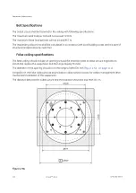


Bolt Specifications
The Substructure shall be fastened to the ceiling with following specifications:
The maximum axial load per bolt will not exceed 7210 N.
The maximum Shear load per bolt will not exceed 957 N.
The maximum pullout force shall be calculated in accordance with local building codes and it is part of
structural analysis done by customer.
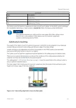
False ceiling specifications
The false ceiling should include an opening around the interface plate to allow service engineers to
install and replace the suspension and the Large Display Monitor.
The diameter of the opening should be in the range of 489-620 mm (
A trapdoor in the false ceiling should be provided to allow service access for cables management after
mechanical installation of the suspension.
The distance between the substructure and the trapdoor should be less than 50 cm.
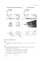
Figure 2-64
Equipment Requirements
114
Innova
TM
IGS 6
5750182-1EN 3
Summary of Contents for Innova IGS 6
Page 9: ...Page intentionally left blank...
Page 57: ...Figure 2 11 Omega V Table dimensions Equipment Requirements 46 InnovaTM IGS 6 5750182 1EN 3...
Page 61: ...Figure 2 14 Gas box outlets Omega Table Equipment Requirements 50 InnovaTM IGS 6 5750182 1EN 3...
Page 69: ...Figure 2 22 C2 Cabinet dimensions Equipment Requirements 58 InnovaTM IGS 6 5750182 1EN 3...
Page 147: ...Page intentionally left blank Environmental Requirements 136 InnovaTM IGS 6 5750182 1EN 3...
Page 158: ...Figure 5 6 PDB Schematic CE 1 2 Electrical Requirements 5750182 1EN 3 InnovaTM IGS 6 147...
Page 159: ...Figure 5 7 PDB Schematic CE 2 2 Electrical Requirements 148 InnovaTM IGS 6 5750182 1EN 3...
Page 161: ...Figure 5 9 PDB Schematic UL 1 2 Electrical Requirements 150 InnovaTM IGS 6 5750182 1EN 3...
Page 194: ...InnovaTM IGS 6...


