45
Appliance Model Number
Model ID #
GFWR4800F / GFWR4805F
3
GFWS3600F / GFWS3605F
2
GHWS2600F / GHWS2605F
1
GFWS2500F / GFWS2505F
0
GFWS3700F / GFWS3705F
5
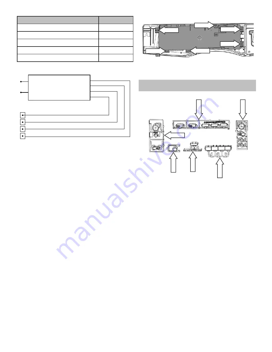
UI Board Strip Circuit
L1
N
IMC J101-3
IMC J101-2
IMC J603-4
IMC J603-3
IMC J603-2
IMC J603-1
+12 VDC
+7.5 VDC
COMM
DC GND
UI J201-5
UI J201-2
UI J201-3
UI J201-1
UI Board Tests
• Run Test 01 for LED operation.
• Run Test 02 for viewing and changing model ID
code.
• Run Test 03 for UI software version.
• Run Test 18 for UI Critical Software Version.
UI Board Diagnostics
1. Check for 120 VAC at IMC J101 pins 2 & 3.
a. If 120 VAC is present go to step 2.
b. If 120 VAC is not present check house supply
voltage.
2. Check for 12 VDC between IMC J603 pins 1 & 4
and 7.5 VDC between IMC J603 pins 1 & 3.
a. If either voltage is not present replace the IMC
board.
b. If both voltages are present go to step 3.
3. Check for 12 VDC between UI J201 pins 1 & 5 and
7.5 VDC between UI J201 pins 3 & 5.
a. If either voltage is not present, check wiring
between the UI board and the IMC board.
b. If both voltages are present, replace the UI
board.
UI Board Removal
1. Disconnect power to the unit.
2. Remove the control panel. (See
Control Panel
Removal
)
3. Remove the six 5/16” hex UI screws.
5/16” Hex
5/16” Hex
5/16” Hex
5/16” Hex
5/16” Hex
5/16” Hex
4. Remove the UI board.
Button Tree
Tree (A)
Tr
ee (B)
Tr
ee (C)
Tr
ee (D)
Tr
ee (E)
Tr
ee (F)
Button trees are used to press the micro switches
on the UI board and to provide a light path between
the LED’s on the UI board and the control panel.
Five button trees are used.
Button Tree Removal
1. Remove the control panel. (See
Control Panel
Removal
)
2. Remove the UI board. (See
UI Board Removal
)
3. Remove button trees:
Button Tree (A)
1. Push the button tree to disengage the front clips.
2. Pivot button tree up to disengage the rear clips.


