45
R E LI AG E A R® LV SG
LO W VO LTAG E S W I TC H G E A R
Notice:
E2.2 and E4.2 circuit breakers
share a common lifting beam. The
lifting beam has two unique
positions for the carabineers to
properly lift each of these circuit
breakers as detailed in Figure 80.
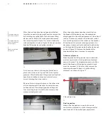
4. Using the switchgear breaker lifting device or a
suitable lifting mechanism and the appropriate
lifting beam, raise the breaker above the
elevation of the cradle draw-out rails.
Warning:
Do not stand under the
circuit breaker during the lifting or
lowering operation.
Notice:
If a breaker is rejected by the
rejection pins, check the breaker
type and rating against the job
drawing.
In addition to the rejection pins previously
described, ReliaGear LV SG cradles will reject Emax
2 circuit breakers which are not configured for
cradle mounted kirklock interlocks if so equipped.
A non-kirklock ready Emax 2 breaker will be
equipped with a bracket on the lower right hand
corner which will interfere with the cradle kirklock
lever.
An Emax 2 circuit breaker can be modified in the
field such that it can be made kirklock ready thus
removing the interference.
Please see
for guidance. A
kirklock ready circuit breaker can be applied in a
cradle that has no cradle mounted kirklock
interlock equipped without issue.
Installing the circuit breakers
Prior to installation
Prior to lifting a breaker to its intended
compartment location, observe the following
precautions:
1. Check the compartment to ensure that it is
free of foreign objects.
2. Verify that the breaker is the correct type
for that compartment.
3. Ensure that the breaker is OPEN.
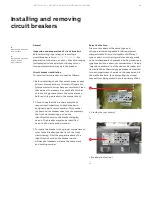
4. Apply a thin fresh coat of lubricating grease to
the breaker’s primary disconnects.
5. Ensure that the position indicator on the circuit
breaker is in in the DISCONNECTED position and
is correctly positioned for initial engagement. To
do this, open the racking handle door and insert
the racking handle and rotate it fully
counter-clockwise.
Installation procedures
To install the Emax 2 circuit breaker, proceed as
follows:
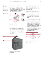
1. Carefully place the breaker in front of the section
in which it is to be installed.
2. Open the breaker compartment door by rotating
the door latch assembly ¼ turn clockwise.
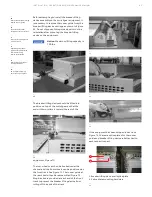
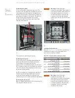
3. Attach the appropriate lifting beam, Table 6, to
the circuit breaker's lifting plates as shown in
Figure 80. The carabineers of the lifting beam
should be securely closed on the circuit breaker's
lifting plates. See
for
guidance on proper use of the circuit breaker's
lifting plates.
Caution:
When using the switchgear
breaker lifting device, do not unwind
the cable completely from the drum.
To lift the breaker, turn the device
operating crank clockwise. To lower
the breaker, turn the device
operating crank counter-clockwise.
—
80
Attaching lifting
beam to Emax 2
circuit breaker
—
80
1. Breaker Lifting Device Hook
2. Lifting Beam
3. E2.2 Carabineer Position (shown)
4. E4.2 Carabineer Position
5. Carabineers
6. Circuit Breaker Lifting Plates
Catalog number
Poles
Description
ELD3E242
3
E2.2 or E4.2 lifting beam
ELD3E62
3
E6.2 lifting beam
Table 6 - Emax 2 lifting beams
1
2
5
6
4
3
DANGER
WARNING
CAUTION
NOTICE
DANGER
WARNING
CAUTION
NOTICE
DANGER
WARNING
CAUTION
NOTICE
DANGER
WARNING
CAUTION
NOTICE


