53
R E LI AG E A R® LV SG
LO W VO LTAG E S W I TC H G E A R
Operation
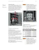
A three position Illuminated Fan Control Switch,
Figure 85, is provided to allow an operator to select
the mode of operation for the cooling fan system.
The fan control switch is provided with a pad-
lockable hasp to allow an operator to lock-out/tag-
out the fan control switch. The three positions of
the fan control switch are “OFF”, “ON” and “TEST”.
The “TEST” position of the fan control switch is a
momentary position.
OFF operating mode
This operating mode may assist with an operator
trouble-shoot or perform maintenance on the fan
cooling system.
With the Illuminated Fan Control Switch in the
“OFF” position, the 120Vac control power to the
fan cooling system is not available except for the
line side of the Fan Control Power Fuse and the
Illuminated Fan Control Switch. All indicating
lights will be off.
ON operating mode
With the Illuminated Fan Control Switch in the
“ON” position, the 120Vac control power to the fan
cooling system is available. The fan control switch
itself will be illuminated and the fan cooling system
is ready to respond as necessary. This is the normal
operating mode for the fan cooling system.
If the current exceeds the values shown in Table 8
for 60 seconds, the amber Current Under Set Value
Light will not be illuminated. The red Fan Relay On
Indicating Light will be illuminated. If the fans are
operating normally, each white Fan On Indicating
Light will be illuminated. If a fan is rotating below
its nominal value, then a failure has occurred and
the white Fan On Indicating Light corresponding to
that fan will not be illuminated. When a fan failure is
detected, load shedding will occur.
If the current drops below the values shown in
Table 8 for 60 seconds, the amber Current Under
Set Value Light will be illuminated. The red Fan
Relay On Indicating Light and all white Fan On
Indicating Lights will be off.
Test operating mode
With the Illuminated Fan Control Switch held in the
“TEST” position, an operator can perform a
functional test on the fan cooling system without
having to exceed the values shown in Table 8.
While the Illuminated Fan Control Switch is held in
the “TEST” position, the following events will
indicate a heathy fan cooling system.
• Amber current under set value indicating light is
not illuminated
• Red fan relay on indicating light is illuminated
• Each white fan on indicating light is illuminated
If the amber Current Under Set Value Indicating
Light is illuminated, check to see if there is a
problem with the fan control switch or with the
EKIP signaling module or the AXTST relay.
If the red Fan Relay On Indicating Lamp did not
illuminate, check to see if the Fan Relay is operating
properly.
If any of the white Fan On Indicating Lamps are not
illuminated, check to see if the fan itself has failed.
Refer to 1VAL106902-TG for instructions on how to
replace a cooling fan.
Notice:
Each cooling fan has a
built-in alarm that indicates if the
fan’s speed has dropped to 40% of
its maximum speed. The white Fan
On Indicating Light will turn off if the
fan’s speed drops below this value.
Load shedding event
For a fan failure event, load shedding will occur.
Two possible causes include:
1. Fan Speed Failure (Ex: Rotor is stuck, debris on
blades hindering fan operation, etc.)
2. DC Power Supply Failure
If load shedding has occurred and one or more of
the white Fan On indicating lamps are not
illuminated, replace the corresponding fans.
If load shedding has occurred and all the white Fan
On indicating lamps are not illuminated, check to
see if the green LED on the DC power supply is
illuminated. If the green LED is not illuminated,
there is a problem with the power supply, and it
needs to be replaced.
If load shedding had not occurred but either a
fan speed failure or DC power supply failure has
occurred, check to see if the load shed relays are
properly engaging.
Maintenance
Cooling fans have a lifetime of ~40,000 hours.
It is recommended to inspect and test the fans
once per year. To test the fans refer to the Test
Operating Mode and Load Shedding Event
sections above.
DANGER
WARNING
CAUTION
NOTICE


