39
R E LI AG E A R® LV SG
LO W VO LTAG E S W I TC H G E A R
—
63
Indoor equipment
weld anchoring
—
64
Spectra series* busway
mounting (front-entry)
Busway connections
Busway runs must be aligned with openings
in the equipment and connected to the mating
components electrically and mechanically.
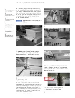
A collar is mounted on the top of the equipment
cable compartment to which is bolted the busway
housing. See Figure 64. The 1/4-20 NC bolts,
washers, and nuts for this mechanical connection
are supplied with the busway stub. The bolts
should be tightened with a torque of 7-9 ft-lbs.
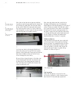
The power conductors in the busway stub are
designed to bolt directly to power connector
blocks mounted on the switchgear riser bus bars.
These connections are made with 1/2-13 NC bolts
supplied with the switchgear equipment.
Notice:
To maintain the minimum
contact resistance across bolted bus
joints, it is recommended that the
joint contact surfaces be coated with
a film of lubricating grease. A can of
this grease is supplied with the
equipment. Do not put grease on the
bolt threads as this will affect the
clamping force exerted by the bolt.
Control wire connections
For external control wiring, refer to Figure 65 for
switchgear cable area dimensions, and connect the
control wires to the switchgear sectionas follows:
1. When control conduits enter the switchgear from
below, they should not extend more than one inch
above the floor. The control wires may be pulled
through the conduits before or after the
switchgear is installed.
—
64
1
1
1
2
2
2
2
5
6
6
4
4
2
2
4
4
3
3
5
Elevation
Plan view
Optional method
Rear
—
63
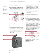
1. Channel sills
2. 3/6 inch fillet weld
3. Front lag sill angle
4. Plug weld in anchor bolt hole
5. Rear sill angle
6. Rear width post
DANGER
WARNING
CAUTION
NOTICE


