33
R E LI AG E A R® LV SG
LO W VO LTAG E S W I TC H G E A R
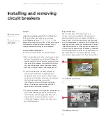
Figure 51 illustrates the installation of the
throughbolts. The throughbolts are in the front
and rear compartments. The nut and bolt assembly
should be tightened with a torque of 25–30 ft-lbs.
—
51
Through-bolt installation
—
52
—
52
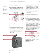
Typical location of
buses at shipping split
All of the hardware required for assembling the
equipment across the shipping splits is furnished
with the equipment. If a transformer is included in
the line-up of equipment, the transformer flange
should be aligned with the opening in the side of
the transition section and fastened together using
the 3/8-16 bolts, nuts and washers supplied with
switchgear. The fastener assembly should be
tightened with a torque of 25-30 ft-lbs.
4. Complete the electrical interconnections -
After completing the mechanical connections
between the several sections of equipment,
the electrical interconnections should be
completed. This includes the installation of splice
plates for the main bus bars, the neutral bus, and
the ground bus in addition to the control and
metering circuits.
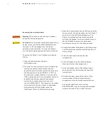
Warning:
All switchgear equipment
must be adequately grounded for
safety. Failure to ground equipment
properly may result in serious injury.
Figure 52 illustrates the general location of
the buses that must be spliced across the
shipping splits.
—
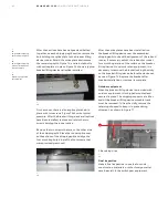
50
Location of through-
bolts (dimension
in inches)
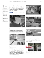
2. Remove the shipping skids - The equipment is
fastened to the shipping skids with ½ inch lag
screws through the equipment anchoring holes.
See Figure 49.
—
49
View showing method of
attaching equipment to
shipping skids
—
49
—
50
—
51
Equipment shipping sections up to 10 feet long will
be fastened to the skids with four lag screws, one
in each corner. The shipping skid and lag screws are
expendable material and may be disposed of at the
purchaser's discretion.
3. Fasten section together - After placement of
the equipment and installing the anchor bolts
loosely, the various shipping sections must be
rigidly fastened together. Throughbolts fasten
each section of the switchgear equipment to the
adjacent section. Figure 50 shows the location of
the throughbolts
Front
3
3
2
Embedded channels (if used)
2
Front
sill angle
Rear
sill angle
Anchor
bolt
1/2 inch
Anchor
bolt
1/2 inch
Floor
surface
Rear
DANGER
WARNING
CAUTION
NOTICE


