29
R E LI AG E A R® LV SG
LO W VO LTAG E S W I TC H G E A R
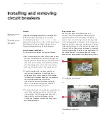
Plan view
Foundation preparation - indoor equipment
Refer to Figure 44 along with the owner's
foundation construction drawings and the
supplemental installation drawings. Although the
indoor switchgear equipment can be mounted
directly on a smooth, level floor, it is recommended
that recessed steel channels be installed for
supporting the equipment. Anchor bolts and
channels are to be provided by the purchaser.
Notice:
When the equipment is installed on a
surface subject to impact (shock) loads due to
operating conditions or environmental seismic
(earthquake) conditions, the anchor bolts should
be fabricated of medium carbon steel
(grade 5 load rating).
The floor channels under the front and rear
switchgear anchor points (see Figure 42) should be
embedded in a level concrete slab with their top
surfaces flush with the finished floor. It is essential
that these steel channels be level and aligned with
each other prior to final anchoring, to prevent
distortion of the switchgear structure, to assure
proper mechanical and electrical connections
between shipping splits, and to assure proper
interfacing to other close-coupled equipment.
—
44
Indoor enclosure
anchor locations
—
44
Embedded “C” Channel, if used
ABB switchgear and load center substations
are frequently mounted on steel floors and/or
structural steel in industrial installations (such
as a mezzanine) to minimize usage of production
floor space.
Regardless of the type of mounting surface, the
requirement for a smooth level surface remains.
If studs or anchor bolts are to be used, they should
be installed in the foundation as it is poured. It is
important that the studs or bolts are spaced to
agree with dimensions given on the job drawings.
The dimensions between anchor bolts for a
particular installation are dependent upon
the configuration of equipment ordered. The
dimensions shown on Figure 44 cover the entire
standard enclosures available for ReliaGear LV
SG switchgear.
Figure 45 illustrates the space available for conduit
and/or cable entrance through the bottom or top
of each equipment section. The space required for
control wiring entry to the optional wiring trough
is also shown.
DANGER
WARNING
CAUTION
NOTICE


