Appendix A: Power Over Ethernet Overview
GE-DS-82 and 82-PoE Ethernet Managed Switch User Manual
221
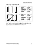
Figure 101: Straight-Through and Crossover Cable
Straight Cable
SIDE 1
SIDE2
SIDE 1
1
1
2
2
3
3
4
4
5
5
6
6
7
7
8
8
SIDE 2
1 = White / Orange
2 = Orange
3 = White / Green
4 = Blue
5 = White / Blue
6 = Green
7 = White / Brown
8 = Brown
1 = White / Orange
2 = Orange
3 = White / Green
4 = Blue
5 = White / Blue
6 = Green
7 = White / Brown
8 = Brown
Crossover Cable
SIDE 1
SIDE2
SIDE 1
1
1
2
2
3
3
4
4
5
5
6
6
7
7
8
8
SIDE 2
1 = White / Orange
2 = Orange
3 = White / Green
4 = Blue
5 = White / Blue
6 = Green
7 = White / Brown
8 = Brown
1 = White / Green
2 = Green
3 = White / Orange
4 = Blue
5 = White / Blue
6 = Orange
7 = White / Brown
8 = Brown
Please make sure your connected cables have the same pin assignment ands color
as the above picture before deploying the cables into your network.
Summary of Contents for 82-POE
Page 26: ...Chapter 2 Installation 22 GE DS 82 and 82 PoE Ethernet Managed Switch User Manual ...
Page 148: ...Chapter 5 Console Management 144 GE DS 82 and 82 PoE Ethernet Managed Switch User Manual ...
Page 212: ...Chapter 6 Command Line Interface 208 GE DS 82 and 82 PoE Ethernet Managed Switch User Manual ...
Page 226: ......

