GCC Technologies LaserPro FMC280 User Manual Download Page 125


121 

232002430G(03)


Keeping  your  LaserPro  FMC280  clean  and  well  maintained  will  ensure  quality  output,  consistent  reliability, 
and  extended  product  life.  Smoke,  dust  or  residue  build-up  inside  the  laser  system  or  the  mechanical 
components can cause  a  reduction  in  the  laser  power,  irregularities in  the  motion  system,  reduced  product 
life  cycle,  and  a  host  of  other  avoidable  problems.  This  section  will  cover  how  to  perform  regular 
maintenance on the worktable, motion system, mirrors, and focal lens. 


The frequency of the cleaning schedule will depend  on number of variables such as the types of material 
you work with, the immediate work environment, the frequency of use, the quality of the exhaust system, etc. 
Clean the machine work tale, drawer, lens on weekly base for normal usage case.  


WARNING


•  Electrical shock may occur if you do not turn off and unplug the LaserPro FMC280 before cleaning. 
•  Damage may occur to the system if you do not turn off and unplug the LaserPro FMC280  and turn off 

laser power supply by key before cleaning. 

•  Always turn off and unplug the LaserPro FMC280 and turn off the laser power supply by key before 

cleaning! 


8.1 Suggested Cleaning and Maintenance Supplies


Cleaning / Maintenance Tool


Special notes


Soap Solution or All-Purpose Cleaner


Paper Towels


Cotton Cloth


Denatured Alcohol


DO NOT use alcohol on any painted surface, 
plastic, or the laser system.


Acetone


ONLY to be used on the work table


Vacuum Cleaner with a Flexible Nozzle


Only to be used in and around the work table 
and motion system


Light Grade Machine Oil


Cotton Swabs


Supplied


Lens Cleaner


1pc supplied, suggest source local supply*


Lint Free Lens Tissue


Supplied


#2 Phillips Screw driver


Allen Wrench .050”


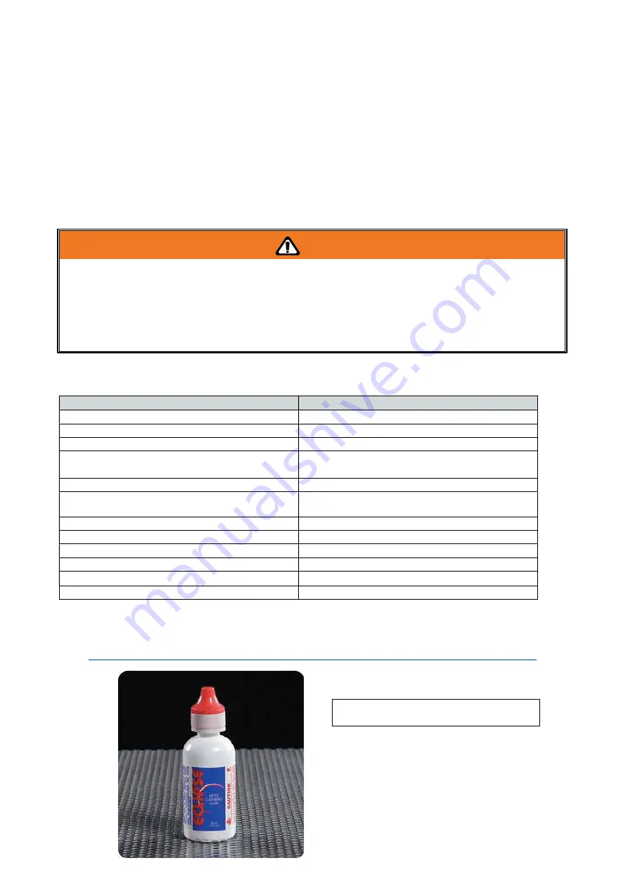
*The  recommended  lens  cleaner  is  Eclipse  Cleaning  System  Solution  from  Photographic  Solutions 
or HPLC grade Methanol. Search “Eclipse Cleaning System Solution” on Amazon or eBay to get the 
solution locally.  

http://www.amazon.com/Photographic-Solutions-ECDCS-Cleaning-Solution/dp/B0000AUR1I


Eclipse Cleaning System Solution 

Summary of Contents for LaserPro FMC280

Page 1: ...www delinit by...

Page 2: ...FMC280 is clearly on the cutting edge of all laser systems GCC understands that a creative technical background is the key to successful growth in the ever changing information economy We have a stro...

Page 3: ...28 4 1 3 1 Networking Connectivity Setup 28 4 1 3 2 Ethernet Connectivity Setup 31 4 2 Graphics Software Setup 37 4 2 1 Recommended Computer Configuration 37 4 2 2 Installation of the LaserPro Print...

Page 4: ...m Option 111 7 1 Fume Extraction System 112 7 2 Rotary Chuck 114 Chapter 8 120 Basic Maintenance 120 8 1 Suggested Cleaning and Maintenance Supplies 121 8 2 Maintaining the Work table 122 8 2 1 Cleani...

Page 5: ...232002430G 03 1 Chapter 1 Safety Principles of a DPSS Fiber Laser Safety Ratings The Safety Interlock System Safety Labels Safety Measures Operating Environment www delinit by...

Page 6: ...he operator to see the exact location where the laser beam will fire Even though the LaserPro FMC280 is equipped with the most powerful laser to date through proper usage and taking necessary hardware...

Page 7: ...ied in any way or removed for any reason Please familiarize yourself with the specific labels and their locations on the machine Below is a list of all the safety labels and their locations on the mac...

Page 8: ...232002430G 03 4 CE Label This label indicates the class level of CE Warning Label Warning Label is written with all the necessary information to be aware of in every operation...

Page 9: ...his label indicates the laser path Normally you can find this label inside of machine Please take extra caution of this area when you conduct maintenance Emergency Stop Label This label indicates the...

Page 10: ...Machine Operation Warning Labels 1 5 Safety Measures LASER RADIATION WARNING Exposure to laser radiation may result in physical burns and severe eye damage Proper use and regular maintenance of this...

Page 11: ...e is identical to the voltage of the machine Do not open the laser access panel when the machine is plugged in Do not attempt to modify or disassemble the laser module Do not attempt to remove or modi...

Page 12: ...ent temperature remains between 15 C and 30 C 60 F to 86 F y Select a location in which the relative humidity remains between 30 40 y Select a location in which there is a short direct path to the fum...

Page 13: ...e from gas tank to FMC280 laser machine 5 Connector for High Pressure Resist Tube and Regulator Valve A high pressure air tube comes with the machine Prepare connector 2 to connect it and Regulator Va...

Page 14: ...bove those necessary to pop the receiver safety valves y Blow off valves should be located on the equipment and shielded so sudden blow offs will not cause personnel injuries or equipment damage y Cas...

Page 15: ...ification y inlet pressure 0 3500 psi 0 250 kgf cm y Outlet pressure 0 310 psi 0 22 kgf cm y Flow volume 140m hr NOTE 1 Make sure the high pressure gas valves and connectors are tightly sealed without...

Page 16: ...s 1 Power on FMC 280 2 Turn on the gas cylinder 3 Adjust the gas regulator valve to proper air pressure Machine Turn Off Procedures 1 Turn off the gas cylinder 2 Click F4 then F2 on the control panel...

Page 17: ...s being reached by upper and lower limbs of the Laser Engraver EN 60825 1 2007 Safety of laser products EN 61000 6 2 2005 Electromagnetic compatibility EMC Part 6 2 Generic standards Immunity for indu...

Page 18: ...14 232002430G 03 Chapter 2 Unpacking Contents Unloading and Unpacking Contents and Accessories Checklist www delinit by...

Page 19: ...he original shipping crate as it may be needed for transportation in the future Unpacking and Unloading The LaserPro FMC280 is shipped in one crate that contains the machine the software and other acc...

Page 20: ...16 232002430G 03 Step 3 Loosen the lock Step 4 Remove the top board and each sideboard...

Page 21: ...p 5 Loosen and remove the pink packing strips by pushing the lock on the strip down and then pull it out towards the top before you can loosen the strips Step 6 Unscrew the screws fastening the slide...

Page 22: ...fastening the slide boards on the pallet then pull them off to form ramps and fix it by screws Step 8 Remove the wooden block from the crate base and then unscrew the four holding stands so that they...

Page 23: ...19 232002430G 03 Step 9 Position the ramps as shown below and the machine can now be pushed off the base board via the ramps...

Page 24: ...butor ITEM QUANTITY Cleaning Kit Cotton Swab 1 Lens Cleaner Solution 1 Lens Tissue 1 Lens Blower 1 Power Cord US EU AU 1 USB Cable 1 Ethernet Cable 1 Safety Goggles 1 4 Ventilation Pipe Connector 1 In...

Page 25: ...232002430G 03 21 Chapter 3 Mechanical Overview Front View Right Profile View Left Profile View Rear View www delinit by...

Page 26: ...h this section regarding the mechanical overview of the LaserPro FMC280 References will be made back to the different parts of the LaserPro FMC280 in later sections 3 1 Front View Lower Front Door Eme...

Page 27: ...232002430G 03 23 3 2 Right Profile View Ethernet Port USB Port Power Socket Main Power Swiych...

Page 28: ...232002430G 03 24 3 3 Left Profile View Water Outlet Water Inlet Assist Air Inlet...

Page 29: ...232002430G 03 25 3 4 Rear View...

Page 30: ...nd Installation Machine Setup Powering Up the Machine Connecting the Computer Graphics Software Setup Recommended Computer Configuration Installation of the LaserPro USB Driver Installation of the Las...

Page 31: ...Machine 1 Connect the male end of the power cord to a quality surge protector and then connect the surge protector to a properly grounded outlet 2 Do the same for the computer system 3 Connect the fe...

Page 32: ...thernet Connectivity Connect the LAN Cable in accessory to the LAN port on the right hand side of the laser system Follow below instruction for ethernet connectivity setup 4 1 3 1 Networking Connectiv...

Page 33: ...232002430G 03 29...

Page 34: ...232002430G 03 30...

Page 35: ...the LAN port of GCC laser engravers and turn on machine Step 2 Navigate the control panel through F4 Function Machine Setting LAN Setup Wizard DHCP OFF Step 3 Navigate the control panel through F4 Fun...

Page 36: ...et device and choose Properties Step 6 Choose the Internet Protocol Version 4 TCP IPv4 and click Properties to open up the setting window Step 7 Enter the IP address and Subnet mask setting values and...

Page 37: ...Device and Printers of computer and right click on the laser machine printer choose Printer Properties Step 9 Select Add Pot under Ports tab and follow the instruction to enter the TCP IP information...

Page 38: ...232002430G 03 34...

Page 39: ...232002430G 03 35...

Page 40: ...232002430G 03 36...

Page 41: ...are not officially supported Any software that can output to the LaserPro Print Driver should work 4 2 1 Recommended Computer Configuration The LaserPro FMC280 operates under Windows operating systems...

Page 42: ...mes up informing you of the detection of a previous driver and asks to keep the existing driver or use the new one select Replace Existing Driver and click Next to continue 9 This screen will prompt y...

Page 43: ...tware which allows you to install Windows OS in MAC computers and run Windows based software under MAC computer and output with GCC print driver 1 Purchase Parallels Desktops on its official website 2...

Page 44: ...232002430G 03 40 4 Enter your Mac OS X User Name and Password then press OK 5 Press Active...

Page 45: ...232002430G 03 41 6 Press OK when activation is complete 7 Register Parallels Desktop...

Page 46: ...232002430G 03 42 8 Press Register and OK to complete the installation of Parallels Desktop 9 Open Parallels Desktop in the Applications folder then choose File New...

Page 47: ...232002430G 03 43 10 Press Install Windows from DVD or image file then press continue to install windows OS 11 Select CD ROM drive with the Windows installation CD...

Page 48: ...430G 03 44 12 Enter the Windows OS product key 13 Select how you would like to run your Windows program 14 After the prior setting is complete the windows OS installation procedure will start automati...

Page 49: ...f the LaserPro Print Driver to install GCC LaserPro Print Driver 16 Install the AP that you want to use after the above installation is complete 4 2 4 Using Autodesk Inventor with GCC LaserPro machine...

Page 50: ...ng area can be found on the paper tab of the windows driver 4 Start sketch 5 Engraving a Finish sketch b Right click on sketch and select properties c Line Type By Layer d Line Weight By Layer e Set c...

Page 51: ...one of the 16 colors available in the pen tab of the windows driver NOTE All objects created in one particular sketch will have the same properties meaning all will engrave or all will cut If you woul...

Page 52: ...ol Panel Navigation Chart Graphic Control Panel Function Pages The LaserPro FMC280 Print Driver Page Setup and Orientation Color Management Using the LaserPro FMC280 Print Driver LaserPro FMC280 Print...

Page 53: ...and off procedure label attached on machine 1 Power on the machine 2 Turn on the gas tank 3 Adjust the gas regulator valve to proper pressure level 4 Turn on the key switch in the front of machine No...

Page 54: ...ast adjustment wheel 5 1 3 Move Lens Carriage Correctly 1 Do NOT move the lens carriage by holding the laser carriage and optical fiber to prevent the damage of machine 3 Correct way to move the carri...

Page 55: ...232002430G 03 51 5 1 4 Work Piece Setup 1 Place the sheet metal piece to the work table on supporting bars 2 Arrange the magnetic fixtures to keep the sheet metal flat Supporting Bars...

Page 56: ...ther outside the tip the focus position moves 3 Once the focus position is properly set tighten the Lock Nut by rotating it clockwise NOTE 1 Proper grounding is critical for LaserPro FMC280 laser syst...

Page 57: ...manual controls easy to do LED Indicator Lights Three indicator lights on the LaserPro FMC280 control panel are part of the system s safety interlock system Door The door light will illuminate when t...

Page 58: ...ile the directional buttons adjust the value of that particular selection Enter Confirms the current selection Start Stop Allows you to start or stop engraving jobs once those jobs have been successfu...

Page 59: ...Other File Management Page Information Air Pressure detect Main Work Page Machine Setting Table Down Carriage Free Red Beam Save position Command Mode Vector Mode File Save Mode Functions Page File I...

Page 60: ...ic job information such as the current job s name Speed Power Freq DPI processing remaining times and jobs loaded Note When you select SmartCENTER from the driver SP option will be available on the ma...

Page 61: ...ally adjust the Y axis and X axis of the laser carriage Carriage Work Table Adjustment Page Relevant Buttons Function F1 Back Back to previous page F3 Down Manually decrease the height of the work tab...

Page 62: ...Down Set Red Beam Carriage Lock Set Command Mode Save Position Flash Memory Set File Save Mode Set Vector Mode Other Reset Machine Information Page this page allows you to view information regarding...

Page 63: ...l jobs and go to the Link DLink Page to set and arrange multiple loaded jobs into a single job queue for processing File Management Page Relevant Buttons Function F1 Back Back to previous page F2 Link...

Page 64: ...layed in the two columns to the right of your file names The first column to the right of your job file name displays the job number of the previous file in the job queue sequence The second column af...

Page 65: ...iew the speed power DPI and Freq settings of the selected job In addition you will be able to go to the File Management Edit Page from this menu to change vector speed and power settings for the selec...

Page 66: ...pond to the same settings found on the LaserPro FMC280 print driver This page allows you to easily adjust these values to make immediate adjustments while processing your loaded jobs even when you hav...

Page 67: ...Red Beam Carriage Free Set Command Mode Save Position File Save Mode Set Vector Mode Other and Reset Machine Setting Page Relevant Buttons Function F1 Back Back to previous page F3 Next Scroll to nex...

Page 68: ...f the red dot laser pointer on the laser carriage Enabling this function will indicate the exact area the engraving laser will fire upon Red Beam YES NO Set Red Beam Page Relevant Buttons Function F1...

Page 69: ...red dot laser pointer on the laser carriage Enabling this function will indicate the position where the laser will fire upon Red Beam YES NO Set Red Beam Page Relevant Buttons Function F1 Back Back t...

Page 70: ...le to manually move the laser carriage along the X and Y axis by hand with the top door open Whereas setting the Carriage Free to NO will lock the laser carriage and movement or positioning can only b...

Page 71: ...ator and more Whereas HPGL mode is a less common output format generated from some RIP applications signage industry Regardless of which format you will be working with both output formats are support...

Page 72: ...s this position to be the origin for subsequent jobs Tip This is an excellent function to use when you are processing identical items or cutting engraving relatively smaller objects positioned away fr...

Page 73: ...mind that speed and quality are usually at a tradeoff The FMC280 200 system s default setting is set to Fine Vector Options Quality Vector Fine Vector Coarse Vector Speedy Vector Slower speed higher q...

Page 74: ...r processing Setting File Save to NO will automatically and immediately delete each job file from the LaserPro FMC280 after the engraving or cutting process Setting File Save to YES will retain all jo...

Page 75: ...the assisted gas is supplied or it s run out of gas the laser machine will show error message to remind when the assisted gas is not detected to ensure optimal cutting result Sensor Switch ON OFF Air...

Page 76: ...the address and use Up or Down keys to change the numbers DHCP ON OFF Please refer to Chapter 4 1 3 for ethernet connectivity setup in computer LAN Setup Wizard Page Relevant Buttons Function F1 Back...

Page 77: ...sensitivity level the HSU laser cutting head will be more sensitive to metal materials including work piece dust and dross Set the sensitivity level per your application and graphics Travel Air funct...

Page 78: ...ck Back to previous page F4 Save Save your current settings Y Z Directional Adjust the X axis scaling numbers U V Directional Adjust the Y axis scaling numbers Start Stop Back to Main Work Page Auto F...

Page 79: ...l system The EOF end of file Alarm setting will enable or disable an audible notification when jobs are complete The Air Delay setting allows you to specify the delay in seconds of the air assist afte...

Page 80: ...store machine settings back to factory default Press ENTER to confirm the change and restart the machine Reset Page Relevant Buttons Function F1 Back Back to previous page Start Stop Back to Main Work...

Page 81: ...rovides you the information regarding the system such as the GCC logo machine name firmware version and other information Information Page Relevant Buttons Function F1 Back Back to previous page U V D...

Page 82: ...revent the cutout falling apart and remove it manually after laser cutting 5 2 1 Node Bridge Installation Step 1 When you install FMC280 print driver the node bridge function will be automatically add...

Page 83: ...232002430G 03 79 Step 3 Click Commands and then Macros from the menu Step 4 Click and drag Module1 Start to the toolbar of CorelDRAW...

Page 84: ...232002430G 03 80 Step 5 Click OK to close the options window Step 6 The installation is completed the node bridge icon will show on the toolbar of CorelDRAW...

Page 85: ...he Node Bridge Cutting window Step 2 Using the PICK TOOL to select object Step 3 Enter the width and length value of the required bridge and press Location button the width setting of node bridge the...

Page 86: ...tward direction of the bridge Step 5 Click Apply button to confirm the setting Step 6 Repeat Step 4 Step 5 to continue generate other node bridges on the cutting path Step 7 After setting up node brid...

Page 87: ...RINTER you may set it up through the graphics software as well The following example takes CorelDRAW to demonstrate how to set up LaserPro FMC280 as the Printer 1 From the primary menu click FILE PRIN...

Page 88: ...on bar on the left click DOCUMENT PAGE SIZE 5 Ensure that NORMAL PAPER and LANDSCAPE are selected 6 Ensure the Paper Width and Height dimensions match the work table dimensions of 712 mm 28inches and...

Page 89: ...olor Management page Disable Color Management or set Color Management to Off CorelDRAW Example Color Management The following is an example of how to properly disable Color Management in the graphics...

Page 90: ...ust your engraving cutting options After you have setup your image design or text to be engraved in your software application you can access the LaserPro FMC280 print driver by going to FILE PRINT PRO...

Page 91: ...rinter The GCC LaserPro print driver will interpret colored and shaded areas as 256 level shades of gray by producing a halftone effect while engraving Instead of engraving only solid lines gray or ha...

Page 92: ...when you select Print from your graphic software program If Print Immediately is not checked then selecting Print will transfer the job file to the machine and will need to be initialized from the Las...

Page 93: ...is acceptable When selected the working area will be extended as well Tip There is a greater performance gain when enabling SmartACT for designs that are vertically longer than they are horizontally...

Page 94: ...232002430G 03 90 After entering the filename and pressing ok the Preview screen will be shown The output file can be previewed and a simulated working time of the job is also displayed...

Page 95: ...r to utilize up to 16 different pens laser parameter settings make sure your graphics software can recognize and utilize the 16 pen colors designated by the LaserPro FMC280 print driver If you would l...

Page 96: ...g or engraving straight lines The machine will automatically slow down when processing curves Power Pen Page The power slider controls the laser s power during operation engraving power with a range s...

Page 97: ...ckbox will process only the raster functions for the areas of your design that correspond to that particular pen color Checking the Vector checkbox will process the vector functions for the areas of y...

Page 98: ...ule of thumb is for every 300 unit increment you will want to adjust the slider by 1 if the final output is 1 unit increment shorter or 1 if the final output is 1 unit increment longer than your graph...

Page 99: ...ector image that has multiple layers without using this mode what may occur is the laser engraver may process the outer vector cutting first and any inner vector cutting will not be possible as your c...

Page 100: ...hen Black White mode Raster function is selected the HSU Disable function will automatically checked to turn off laser cutting head to automatically detect gap between working object and the laser cut...

Page 101: ...232002430G 03 97 5 3 4 4 LaserPro FMC280 Print Driver Paper Page...

Page 102: ...of your square may be slightly offset with every consecutive engraved even or odd line protruding past the square s ideal edge This occurrence may occur on the left or right side of the square and ca...

Page 103: ...ck the Rotary Fixture function and notice the change in the Paper Size fields under Paper Size the X value represents the length of your work piece Enter the length of your work piece in this field 2...

Page 104: ...ffers a number of advanced Raster Engraving output options Contrast Raster Page This provides a quick and easy way to immediately adjust the contrast of an engraved image Moving the slider to the Dark...

Page 105: ...ter engraving via the dithering method This mode will allow you to select the Pattern Type and Dithering Matrix and Enhanced Dithering Pattern Type Dot Bayer Corner 45 Degree Each pattern type uses a...

Page 106: ...from three diffusion types Floyd Stucki and Jarvis Diffusion Type Floyd Stucki Jarvis DEFAULT SETTING Floyd Each diffusion type presents the shade of image as different spread halftones instead of do...

Page 107: ...232002430G 03 103 Chapter 6 Cutting Techniques Vector Cutting Cutting Large Work Piece 3D Tips Modify Image Settings of Picture for Better Engraving Quality...

Page 108: ...ide of the screen 3 Change the outline color of the selected characters outline by right clicking on the desired color from the CorelDRAW Color Palette 4 Change the selected characters outline thickne...

Page 109: ...arts follow below procedures for setup Youtube video is also available for quick reference https www youtube com watch v dEHyzKPzU_Q Step 1 Remove all the supporting bars on working platform with scre...

Page 110: ...toFocus button on control panel FMC280 laser system will automatically find the optimum focal distance for best laser cutting quality Step 5 Set up the laser parameters on LaserPro print driver and pr...

Page 111: ...the computer by USB cable 2 Download the picture from the digital camera to the computer 3 Select the picture that you want to engrave 4 Import the image from the folder where the picture is located...

Page 112: ...232002430G 03 108 6 Change the Bitmap settings by setting Color to Grayscale 8 bit and Resolution to 300 dpi and click OK 7 Finally Invert the image by selecting Effects Transform Invert...

Page 113: ...232002430G 03 109 8 Now you are ready to output the modified image by clicking File Print...

Page 114: ...r general use There are many tips and tricks to achieve a good engraving quality It takes a lot of practice and experience to achieve a good engraving quality Different picture may need different modi...

Page 115: ...232002430G 02 111 Chapter 7 Optional Items Air Extraction System Option Rotary Chuck Option www delinit by...

Page 116: ...umulated within the work table In order to ensure personnel safety and legal compliance GCC LaserPro FMC280 is required to connect with an explosion proof fume extraction system You can source fume ex...

Page 117: ...ed tubing such as PVC or sheet metal with a 4 diameter to the ventilation opening located on the rear side of the LaserPro FMC280 As shown in the picture below Try to keep this tubing as straight as p...

Page 118: ...ates the working object up to 360 to allow for engraving cutting on cylindrical or circular objects Work Piece Limitations Maximum Length 410 mm 16 1 inches Maximum Loading Weight 4 kg 8 8 lbs Minimum...

Page 119: ...Align and fix the Rotary Chuck to the No 5 screw opening on the Supporting Bars 4 Fix the other three screws accordingly 5 Open the front door of the FMC280 laser machine and connect the Rotary Chuck...

Page 120: ...ary Chuck prior to start work by lowering the work table down first LOADING OBJECTS To load the working object to Rotary Chuck you can use the enclosed tools to widen or tighten the metallic claws Sim...

Page 121: ...detached and reverted for better fitting objects with different sizes Note that the clamps should be assembled by lining up the correct numbers Please remember to lubricate the detachable clamps alon...

Page 122: ...tary Chuck load the work piece onto the Rotary Chuck by centering the object to the clamping end and adjustable rear end Adjust the leveling screws on the rear end of Rotary Chuck to make sure the wor...

Page 123: ...meter value represents the diameter of your working piece where the laser works Enter the diameter of your work piece in this field Again remember the proper diameter value would be the diameter locat...

Page 124: ...ance Supplies Maintaining the Work table and Motion System Accessing the Work table and Motion System Cleaning the Work table and Motion System Lubrication of the Y Rails Cleaning the Optics System Re...

Page 125: ...o the system if you do not turn off and unplug the LaserPro FMC280 and turn off laser power supply by key before cleaning Always turn off and unplug the LaserPro FMC280 and turn off the laser power su...

Page 126: ...drawer as well CAUTION Never pour or spray alcohol or acetone directly to the work table Oil alcohol and acetone can cause fires or smoke build up if improperly used 8 3 Cleaning the Optics System 8...

Page 127: ...ge 5 Drape a new sheet of lens tissue over the mirror 6 Apply a few drops of lens cleaner on the tissue covered mirror apply enough so that the tissue absorbs just enough solution to cover the mirror...

Page 128: ...124 232002430G 03 Chapter 9 Appendix LaserPro FMC280 Specification Sheet www delinit by...

Page 129: ...d 20IPS Computer Interface 10 Base T Ethernet Full Speed 2 0 USB port Display Panel 4 line LCD panel showing current file name total working time laser power cutting speed file s loaded into memory bu...

Reviews: