88
b.
Installation of E200 Rotary Attachment
1) Turn off the power of the laser engraver
2) Open the front panel of the machine, lower the working platform to its bottom
3)
When placing the rotary attachment on the working table, the rotary attachment can only
apply the small conical fixtures to work with small objects of diameters.
4)
If working with bigger objects are required, remove the working table by releasing the four
thumbscrews towards the sides and place the rotary attachment on the bottom tray. Under
this condition, Rotary Attachment can use either the small or large conical fixtures
5) Line up the rotary attachment to the left hand side of the working area and towards the mid-
section of the working area.
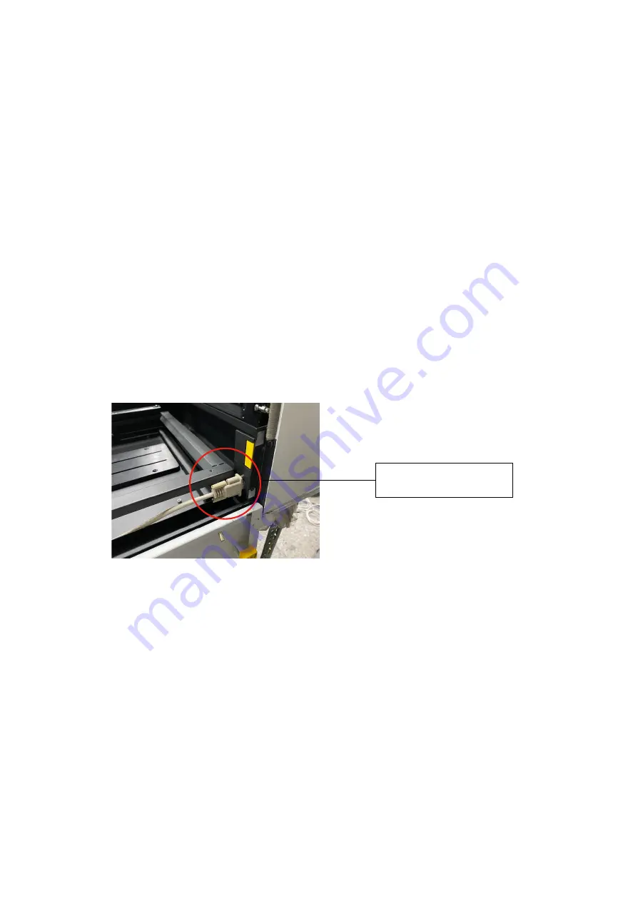
6) Connect the rotary attachment cable to the rotary attachment port located inside the machine
(shown in the picture below)
7) Close the front door panel.
8) The rotary attachment is now properly installed.
9) Power on the LaserPro E200 and the rotary attachment will be automatically detected and
the engraving table will automatically move to its lowest position.
Rotary Attachment Port
OPERATION:
1) Use a ruler to measure the diameter (at the point on the work piece you will be engraving)
and length of the work piece you will be engraving. Make a record of this.
2) Load the work piece onto the rotary attachment
a) First lift the rear-end lever of the rotary attachment to release the adjustable end of rotary
attachment.
b) Load the work piece by centering its open end against the front fixture and slide the
adjustable end to fit the bottom of work piece firmly.
c) Lower down the lever to secure the work piece with the rotary attachment.
3) Manually move the laser carriage to the proper X/ Y location on the work object where you
will do laser engraving or cutting. Hit the Auto Focus button on control panel and the laser
machine will now properly focus at the location to be laser engraved or cut.
Summary of Contents for LaserPro E200 Series
Page 13: ...12 Chapter 2 Unpacking Unloading Unpacking...
Page 19: ...18 3 3 Right Profile View 3 4 Left Profile View...
Page 20: ...19 3 5 Rear View...
Page 21: ...20 3 6 Water Chiller Front View...
Page 22: ...21 3 7 Water Chiller Right View 3 8 Water Chiller Left View 3 9 Water Chiller Rear View...
Page 23: ...22 Chapter 4 Machine Setup Water Chiller Setup E200 Desktop Laser Engraver Setup...
Page 31: ...30 2 Click Next 3 Clip Launch SmartJOB and clip Finish...
Page 36: ...35 5 Choose the WiFi connection 6 WiFi Setting is complete...
Page 70: ...69 7 4 E200 Touch Panel Operation 7 4 1 Navigation Chart of E200 Touch Panel...
Page 81: ...80 Chapter 8 Optional Items Fume Extraction System Air Compressor Rotary Attachment...
Page 99: ...Chapter 10 Appendix GCC LaserPro E200 Specification Sheet...


