www.gateway.com
79
4
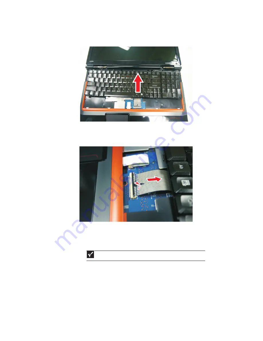
Lift the back edge of the keyboard slightly, then slowly slide it toward the LCD
panel to release the keyboard retaining tabs located on the front edge of the keyboard.
5
Slide the keyboard connector clip to the back of the notebook or lift the connector
clip off of the cable, then slide the cable out of the clip. Be careful not to touch or
damage any other components.
6
Place the new keyboard keys-up on your notebook with the space bar toward you.
7
Make sure the keyboard connector clip is fully moved toward the back of the
notebook or lifted into the raised position, insert the cable into the connector, then
slide the clip forward or downward to lock the connector in place.
Important
The keyboard cable is correctly oriented if it is not twisted.
Summary of Contents for P-79
Page 1: ...P 79 SERVICEGUIDE...
Page 5: ...iii www gateway com...
Page 6: ...Contents iv...
Page 11: ...www gateway com 5 System block diagram...
Page 40: ...CHAPTER 1 System specifications 34...
Page 144: ...CHAPTER 3 Replacing notebook components 138...
Page 163: ...CHAPTER5 157 Connector locations System board top connectors System board bottom connectors...
Page 164: ...CHAPTER 5 Connector locations 158 System board top connectors...
Page 165: ...www gateway com 159 System board bottom connectors...
Page 166: ...CHAPTER 5 Connector locations 160...
Page 167: ...CHAPTER6 161 FRU Field Replaceable Unit list Introduction Exploded diagram FRU list...
Page 169: ...www gateway com 163 Exploded diagram Notebook chassis...
Page 185: ...APPENDIXA 179 Model definition and configuration...
Page 186: ...APPENDIX A Model definition and configuration 180 TBD...
Page 187: ...APPENDIXB 181 Test compatible components Introduction Microsoft Windows Vista Environment Test...
Page 191: ...APPENDIXC 185 Online support information...
Page 196: ...Index 190...
Page 197: ......
Page 198: ...MAN P 79 SVC GDE R1 06 09...


