background image

44 

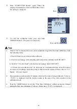
  Perform leak check. If there is no air leakage, the 

replacement is completed. For details, refer to 

“7.6 Leak Check”. 


8.2 Checking the Total Operating Time of the Air Pump


The total operating time of the built-in air pump is recorded and can be checked by the user. Use this 

information as a guide when using more than one GSP-501FT properly or to know when the 

maintenance time. 


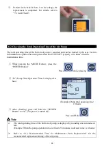
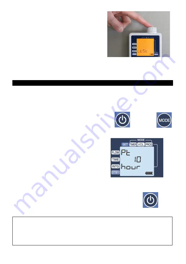
  While pressing the “MODE  Button”, press the 

“POWER Button”. 


Press 

 while pressing  


  “Pt” (Pump Total Operation Time) is displayed in 

hour. 


(Example) Pump total operating time:  

10 hours 


  After checking, press and hold the “POWER 

Button” to exit. (The power is turned off.) 

Press and Hold 


 Note


The total operating time of the built-in air pump is displayed by rounding down minutes or 

less. 

(Example: When the pump operation time is 4 hours 58 minutes, indicated value is 4 hours.) 


Refer to “11.3  Recommended Time for Maintenance Parts Replacement”  for the 

recommended replacement timing of the air pump.


Summary of Contents for GSP-501FT

Page 1: ...mp GSP 501FT Important Notices Please read this manual thoroughly before using this product Keep this manual with this product Gastec Corporation 8 8 6 Fukayanaka Ayase City Kanagawa 252 1195 Japan TEL 0467 79 3910 FAX 0467 79 3979 IM23GSP501FTE1 ...

Page 2: ...th the Previous Sampling Setting 27 6 7 Display of Sampling Information during Sampling Operation 29 6 8 Display of Setting Information during Sampling Operation 29 6 9 Stop the Sampling Operation 29 6 10 Auto Power Off 29 6 11 Clogging 30 6 12 Intermittent Operation 30 7 Flow Calibration 31 7 1 About Flow Calibration 31 7 2 Calibration Mode 31 7 3 Setting of Flow Rate Conversion Temperature 32 7 ...

Page 3: ...his product properly be sure to observe the following precautions The precautions are critical for safety This product should be used by specialists with knowledge of environmental measurements This product is an automatic air sampling pump Do not use the product for purposes other than air sampling of various Gastec gas detector tubes sorbent tubes etc Gastec Corporation shall not take responsibi...

Page 4: ... generation devices such as professional radios and amateur radios within 30cm from this product If electromagnetic wave generation devices are used near this product errors may occur in the measured flow rate Do not disassemble or modify the product The safety and quality of the product cannot be guaranteed Be sure to turn off the power before replacing the battery Mechanical failure may result D...

Page 5: ...please check that all the following items are present Item Product code Quantity Model GSP 501FT Unit 1 Detector Tube Adapter GSP300 13 1 AAAlkaline Batteries Panasonic Corporation LR06 2 Dust Filter 5 pcs 1 Tube Tip Holder 722 1 Instruction Manual 1 ...

Page 6: ...5 4 Design and Basic Features 4 1 Names and Functions ...

Page 7: ...ted using six buttons For details see 4 2 Description of the LCD and Operating Buttons Status Lamp The light colour and flashing indicate the operation status Battery Chamber Battery Chamber Cover Set two AA alkaline batteries or AA nickel metal hydride batteries in the battery chamber The battery chamber cover is opened and closed by sliding it while pressing it with your finger when replacing th...

Page 8: ... It flashes while the program is being selected Battery Level Indicator AA Batteries The remaining battery power in the battery chamber is displayed in five levels Refer to 5 1 3 Relationship between Battery Level Indicator and Sampling Time for remaining battery power Unit The unit is displayed according to the displayed values Set Value Measured value Each set value is displayed during setting a...

Page 9: ...lts C Select Button Switches the items to be changed instantaneous flow rate sampling time integrated volume and standby time in order Press this button during pump operation to check the current sampling operation setting D Increase Button Press this button to increase the setting value In the program mode the registration number is switched E Decrease Button Press this button to decrease the set...

Page 10: ...ies It is recommended to use AA nickel metal hydride batteries when the flow rate is high and the suction load is high or when the product is used at low temperatures 5 1 2 How to Install and Replace AA Batteries Note Ensure to turn off the power before installing or removing the batteries Mechanical failure may result Slide the battery chamber cover toward the rear side while pressing it and then...

Page 11: ...cked by sliding it toward the back side without pressing it Note Note that the power will not be turned on if the battery is installed in the wrong direction Check if the battery cover is locked before use The cover may open due to impact or vibration which may interfere with energization and cause unexpected power failure If the electrode is dirty wipe it with a dry cloth before use Otherwise thi...

Page 12: ...ery level indicator and the sampling time 2 AA nickel metal hydride batteries typical example Sampling condition Sampling time hours Flow rate mL min Load kPa 50 30 1 15 13 5 1 0 3 100 1 5 29 17 7 2 0 5 100 20 2 17 14 5 2 0 3 200 2 23 20 10 4 1 2 500 10 6 4 6 5 1 0 3 Note The values in Tables 1 2 are typical examples at a temperature of 25 C and atmospheric pressure of 1 atm Please note that these...

Page 13: ... starting up the pump factory default conversion temperature 25 C How to check the flow rate conversion temperature Press the Power Button to turn on the power When activated the followings are displayed in order All segments light up for 2 seconds Flow Rate Conversion Temperature for 2 seconds Previous Sampling Results Check at the timing of above When the flow rate conversion temperature is 25 C...

Page 14: ...Do not block the air outlet port Flow resistance may cause errors in the instantaneous flow rate and integrated volume The outflow rate from the air outlet port is out of the guaranteed flow rate accuracy Also be careful of the following items regarding placing the pump Note Select a place with little airflow and little fluctuation of atmospheric pressure and install the pump with the inclination ...

Page 15: ... Timer mode or Volume Mode is saved in advance and the setting is read out to perform sampling This is useful when using the same sampling setting repeatedly The maximum number of sampling settings that can be stored is 5 Sampling can be performed with the same setting as the previous one by starting the pump while Previous Sampling Setting or Previous Sampling Result are displayed Note The operat...

Page 16: ...isplayed Mode Timer FLOW TIME 0 00 INTG 0 000L STBY Previous sampling results above is when purchased Press MODE Button to select the Timer mode Press Check that the set value of Instantaneous flow rate is blinking and set the desired instantaneous flow rate with the Increase Button and Decrease Button Press and hold to make fast forward Setting range 50 500mL min The setting increment is 1mL min ...

Page 17: ...ous sampling Setting procedure When 0 01 is displayed press DECREASE Button once When 30 00 is displayed press INCREASE Button once When Time is set to is also displayed at the Integrated volume position Press Example Sampling time 10 min Press or To set the standby time press SELECT Button to make the Standby setting value blink then set the desired standby time with the INCREASE Button and DECRE...

Page 18: ...een and the sampling operation starts If the standby time is set the followings are displayed FLOW TIME INTG and the sampling operation starts when the remaining standby time becomes 0 00 Press and Hold Pump running On standby After the set sampling time has elapsed the sampling operation is completed and the sampling result is displayed ...

Page 19: ...n to turn off the power Press and Hold Note To repeat sampling with the same settings press and hold the Start Stop Button in the state described in and above to start the sampling operation 6 4 Volume Mode Note The integrated volume rate cannot be set to beyond 30 hours of sampling See the settable range in the graph below Example When the instantaneous flow rate is set to 10 mL min intermittent ...

Page 20: ...Press MODE Button to select the Volume Mode Press twice Check that the set value of Instantaneous flow rate is blinking and set the desired instantaneous flow rate with the INCREASE Button and DECREASE Button Press and hold to make fast forward Setting range 10 500mL min The setting increment is 1mL min When the instantaneous flow rate is set at 10 to 49mL min the pump runs intermittently with the...

Page 21: ...ampling time is automatically calculated and the value is displayed at the Time position Set to for continuous sampling Setting procedure When 0 010L is displayed press DECREASE Button once When 900 0 is displayed press INCREASE Button once When Integrated volume is set to is also displayed at the Time position Press Example Integrated volume 1 L Press or To set the standby time press SELECT Butto...

Page 22: ...displayed FLOW TIME INTG and the sampling operation starts when the remaining standby time becomes 0 00 Press and Hold Pump running On standby Example Standby time 5 min When the set integrated volume is reached the sampling operation is completed and the sampling result is displayed The screen is switched by pressing the SELECT Button and the settings mode instantaneous flow rate sampling time in...

Page 23: ...in and above to start the sampling operation 6 5 Program Mode 6 5 1 How to Save and Change the Program When the pump is turned on by pressing the POWER Button the flow rate conversion temperature is displayed for 2 seconds and then the sampling results in the previous operation are displayed Previous sampling results Press MODE Button to select the Program mode Press three times ...

Page 24: ... Example Program registration number When the SELECT Button is pressed and held the program number is switched from blinking to a steady light allowing the program to be set For program settings please refer to to of 6 3 Timer Mode and to of 6 4 Volume Mode Press and Hold Example Timer mode Flow rate 200 mL min Sampling time 10 min Confirm that the mode the instantaneous flow rate sampling time in...

Page 25: ...Button the flow rate conversion temperature is displayed for 2 seconds and then the sampling results in the previous operation are displayed Previous sampling results Press MODE Button to select the Program mode Press three times Check that the program number is blinking and then select the program number to be changed the number blinks with the INCREASE Button and DECREASE Button Program numbers ...

Page 26: ...rrectly for the selected program mode When the sampling is ready press and hold the START STOP Button The status lamp flashes in green and the sampling operation starts If the standby time is set the followings are displayed FLOW TIME INTG and the sampling operation starts when the remaining standby time becomes 0 00 Press and Hold Pump running On standby Example Standby time 5 min ...

Page 27: ...mber and the setting of the saved setting mode instantaneous flow rate sampling time integrated volume and standby time Press Example Timer mode Flow rate 200 mL min Time 10 min Press and hold the POWER Button to turn off the power Press and Hold Note To perform sampling with the same settings press and hold the Start Stop Button in the state described in and above to start the sampling operation ...

Page 28: ...stantaneous flow rate set sampling time calculated integrated volume and set value of standby time at the previous sampling Press Previous sampling setting Check that the mode instantaneous flow rate sampling time integrated volume and standby time are set correctly When the sampling is ready press and hold the START STOP Button The status lamp flashes in green and the sampling operation starts If...

Page 29: ...d the sampling result is displayed Press the SELECT Button to switch the screen and display the setting of the sampling performed mode program number In case of program mode instantaneous flow rate sampling time integrated volume and standby time Press Press and hold the POWER Button to turn off the power Press and Hold ...

Page 30: ...rent sampling operation setting mode program registration number in case of program mode instantaneous flow rate sampling time integrated volume and standby time 6 9 Stop the Sampling Operation The sampling operation can be stopped by pressing and holding the START STOP Button during standby or sampling operation At this time the sampling result sampling time integrated volume at the time is displ...

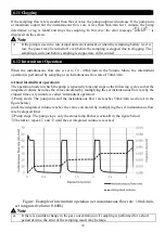
Page 31: ...ow rate of 50mL min About intermittent operation The operation mode in which the pump is repeatedly runs and stops as the following cycles so that the integrated volume becomes the value calculated by multiplying the set instantaneous flow rate by the elapsed time every minute is called intermittent operation Pump starts The pump runs and the instantaneous flow rate reaches 50mL min section A in t...

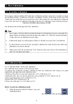
Page 32: ...ion becomes large Calibrate the pump in a stable position Shock or vibration can cause errors in calibration Use short tubes to connect devices as possible Shorter tubes make the flow rate stable and calibration error can be reduced Make sure to clear the air outlet port Flow resistance may cause errors in the instantaneous flow rate and integrated volume 7 2 Calibration Mode Use Calibration Mode ...

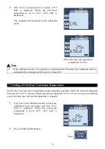
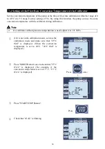
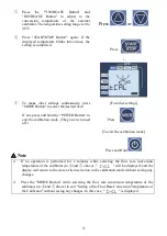
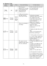
Page 33: ...terminated and the power is turned off 7 3 Setting of Flow Rate Conversion Temperature Set the flow rate conversion temperature during sampling operation Select the desired temperature between 20 C or 25 C factory default conversion temperature 25 C It is not necessary to recalibrate even if the flow rate conversion temperature is changed If it is not in the calibration mode activate the calibrati...

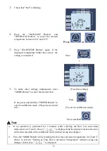
Page 34: ...R Button to exit the calibration mode The power is turned off For other settings Press To exit the calibration mode Press and Hold Note If no operation is performed for 2 minutes while selecting the flow rate conversion temperature in and above is displayed and the display returns to the state of the item selection in the calibration mode without saving any changes Press the MODE Button while sele...

Page 35: ... calibrator during calibration Note If a calibrator without pressure compensation is used adjust it to 101 3kPa If it is not in the calibration mode activate the calibration mode and make sure that 25 C tStd is displayed When the conversion temperature is set to 20 C 20 C tStd is displayed Press MODE Button once to check that 25 C tCAL is displayed For example if the conversion temperature is set ...

Page 36: ...the calibration mode The power is turned off For other settings Press To exit the calibration mode Press and Hold Note If no operation is performed for 2 minutes while selecting the flow rate conversion temperature of the calibrator in and above will be displayed and the display will return to the state of item selection in the calibration mode without saving any changes Press the MODE Button whil...

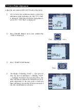
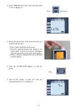
Page 37: ...C 20 C tStd is displayed Press MODE Button twice and confirm that 0AdJ is displayed Press twice Press START STOP Button Press The display of blinking 0AdJ Zero point of flow rate prior to calibration blinking 0AdJ blinking 0mL min Zero point of flow rate after calibration indicates the completion of zero point adjustment If the zero point is 0mL min after calibration it is normal If it does not re...

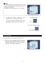
Page 38: ...y press MODE Button to select the desired item If not press and hold the POWER Button to exit the calibration mode The power is turned off For other settings Press To exit the calibration mode Press and Hold 7 6 Leak Check Ensure that there is no air leakage inside GSP 501FT If it is not in the calibration mode activate the calibration mode and make sure that 25 C tStd is displayed When the conver...

Page 39: ...ger against the suction port Attach the supplied detector tube adapter to the suction inlet and insert an unused unbroken detector tube into the suction port of the adapter Attach a crack free tubing to the suction inlet and bend the tubing Press the START STOP Button to start the pump Press After L tSt blinks it turns off Then the instantaneous flow rate is displayed ...

Page 40: ...g the leak check L Err is displayed there is a possibility of air leakage Please check the items described below i Activate the calibration mode perform the zero point adjustment referring to 7 5 Zero Point Adjustment and then perform the leak check again ii Remove the suction inlet and check that there is no dust cracks etc on the sealing O ring and check that there is no dust or scratches on the...

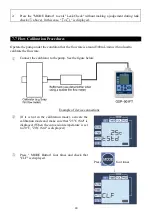
Page 41: ...ate is around 300mL min with no load to calibrate the flow rate Connect the calibrator to the pump See the figure below Example of device connections If it is not in the calibration mode activate the calibration mode and make sure that 25 C tStd is displayed When the conversion temperature is set to 20 C 20 C tStd is displayed Press MODE Button four times and check that CLF is displayed Press four...

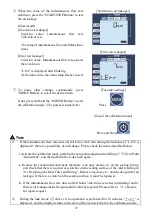
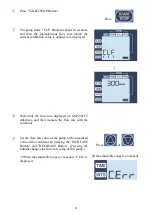
Page 42: ...l the flow rate displayed on GSP 501FT stabilizes and then measure the flow rate with the calibrator Press or If the adjustable range is exceeded Set the flow rate value of the pump to the measured value of the calibrator by pressing the INCREASE Button and DECREASE Button Pressing the buttons changes the flow rate value of this pump When the adjustable range is exceeded C Err is displayed ...

Page 43: ...en the calibrator and GSP 501FT iii Refer to 7 6 Leak Check and check for air leakage inside GSP 501FT iv If there are no problems with i iii there may be a mechanical failure of the flow sensor or circuit or air leakage inside the pump so that it must be repaired Please refer to 11 1 Repair for repair request If no operation is performed for 10 minutes while the flow rate is being calibrated abov...

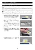
Page 44: ... the suction inlet counterclockwise while pressing it downward to remove it from the main unit When the inlet is turned it rises up Remove the O ring and dust filter from the suction inlet The O ring and filter may remain on the main unit side In this case tilt the main unit or use tweezers etc to remove the O ring and filter Place a new dust filter and a new O ring to the suction inlet Align the ...

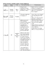
Page 45: ...ime While pressing the MODE Button press the POWER Button Press while pressing Pt Pump Total Operation Time is displayed in hour Example Pump total operating time 10 hours After checking press and hold the POWER Button to exit The power is turned off Press and Hold Note The total operating time of the built in air pump is displayed by rounding down minutes or less Example When the pump operation t...

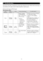
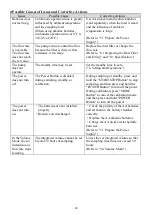
Page 46: ...ermittent operation this error is not detected The flow rate may not reach the set value due to a large resistance of the sampling media Check if the flow resistance of the sampling media at the set flow rate is within the specifications of the pump Refer to 10 Specifications Blinking Flashing red light Low Battery The remaining battery level is getting low Replace with new AA alkaline batteries o...

Page 47: ...ntegration Error When timer mode If the measured integrated value falls out of 5 of the value calculated from multiplying the set sampling time by the flow rate the error message is displayed after the pump stops When Volume Mode If the actual sampling time is out of 5 of the value calculated from the set integrated value and flow rate In intermittent operation if calculated sampling time 1 minute...

Page 48: ...ht Leak Error There is a possibility of air leakage Perform the zero point adjustment again Refer to 7 5 Zero Point Adjustment Replace the dust filter and O ring Refer to 8 1 Replacing the Dust Filter and O ring If the problem is not solved in and there might be air leakage inside the pump and must be repaired Refer to 11 1 Repair Flashing red light Span Error The sensor is out of adjustable range...

Page 49: ...tandby time may be set Set the standby time to zero 6 Setting and Operations The power does not turn off The Power Button is disabled during sampling standby or calibration During sampling or standby press and hold the START STOP Button to stop sampling and then press and hold the POWER Button to turn off the power During calibration press MODE Button to cancel the calibration mode and then press ...

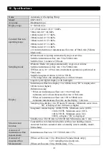
Page 50: ...th backlight Instantaneous flow rate display 0 to 600mL min Hi is displayed at 601mL min or higher Minimum scale When set instantaneous flow rate 10 to 99mL min minimum scale of instantaneous flow rate 0 5mL min When set instantaneous flow rate 100 to 500mL min minimum instantaneous flow rate on the display 1 mL min Sampling time display 0 to 99 hours 59 minutes Minimum scale 1min Hi is displayed ...

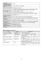
Page 51: ...d regulations EU Directive 2014 30 EU EMC 2011 65 EU EU 2015 863 RoHS UK Regulation 2016 No 1091 EMC 2012 No 3032 RoHS EMC harmonised standards EU EN 61326 1 2013 UK BS EN 61326 1 2013 RoHS designated standards EU EN IEC63000 2018 UK BS EN IEC63000 2018 Optional Replacement parts Item Model Description Belt loop pump holder GSP500FT 30 Case for personal wear Dust filters and O rings GSP500FT 40 5 ...

Page 52: ...FACILITIES OR THE SHORTEST PERIOD THAT IS PERMITTED BY APPLICABLE LAW GASTEC SHALL NOT BE LIABLE FOR ANY DAMAGES CAUSED BY ANY DELAY IN THE DELIVERY OF PRODUCTS NEITHER SHALL GASTEC BE LIABLE PURSUANT TO THIS WARRANTY FOR ANY INDIRECT INCIDENTAL SPECIAL AND OR CONSEQUENTIAL DAMAGES HOWEVER CAUSED AND REGARDLESS OF THE THEORY OF LIABILITY INCLUDING BUT NOT LIMITED TO COMPENSATION REIMBURSEMENT AND ...

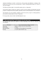
Page 53: ...rly those used with hazardous or toxic substances This Warranty may not be modified expanded or altered in any way except in a writing signed by a fully authorized representative of Gastec Corporation For any questions please contact international gastec co jp 11 3 Recommended Time for Maintenance Parts Replacement The following parts need to be replaced It varies depending on the actual use frequ...

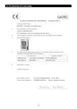
Page 54: ...53 12 Declaration of Conformity ...

Page 55: ...54 22I MP ...

Reviews: