background image

37

GETTING START-

ED

Using the GOTO

Key

Sounder Setup Page (con’t.)

To use Auto Calibration:

1. Ensure ‘Auto Calibrate?’ is displayed in the speed calibration field. If it is not, press

O

to display the calibration menu.

2. Highlight ‘Auto Calibrate’ and press 

T

.

3. Press 

T

again and an instruction message will appear.

4. Read the instructions and press 

T

when you are ready to begin calibration.

5. Slowly accelerate your boat to a maximum safe cruising speed and then back

down to a stop and press 

T

. The minimum and maximum speed which the unit

is now calibrated for will be displayed in the ‘calibrated range’ field.

6. Auto calibration is complete.

When 

manual calibration

mode is selected, the speed calibration bar will

appear as a white horizontal strip with a black slider bar.

Before entering the calibration, you will need to compare the value shown on

the speed calibration field’s STW display, with your boat’s actual speed as deter-
mined by the speedometer or by using a stop watch. Accelerate to a safe speed and
compare the two speed readings.

SECTION

3

SOUNDER PAGE

Speed Calibration Setup
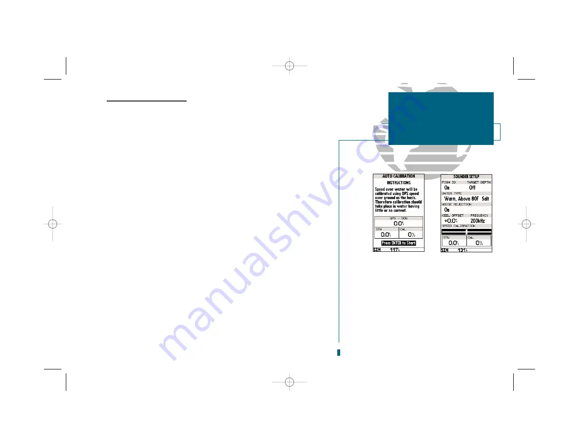
A

B

A.

When you are ready to begin calibration, read
the instructions and press EDIT/ENTER.

B.

When manual calibration mode is selected, the
speed calibration bar will appear as a white hori-
zontal strip, with a black slider bar positioned in
the middle.

19000138.10A.QXD  11/11/99  8:47 AM  Page 37

Summary of Contents for GPSMAP 235 Sounder

Page 1: ...GPSMAP 235 Sounder TM OWNER S MANUAL AND REFERENCE 19000138 10A QXD 11 11 99 8 46 AM Page 1...

Page 2: ...1 44 1794 519222 GARMIN Asia Corp 3th Fl No 1 Lane 45 Pao Hsing Road Hsin Tien Taipei Taiwan R O C Tel 011 886 02 2917 4107 Fax 011 886 02 2917 1758 All rights reserved No part of this manual may be r...

Page 3: ...e reserved The GPSMAP 235 Sounder should not be used as a navigational aid or depth sounder to prevent collision grounding or boat damage any of which could result in personal injury For reasons of sa...

Page 4: ...n accordance with the instructions may cause harmful interference to radio communications There is no guarantee that interference will not occur in a particular installation If the sounder does cause...

Page 5: ...ng 250 alphanumeric waypoints with selectable icons and comments Built in database usable from 4096 to 64 nm worldwide and to 32 nm in the continental United States 20 reversible routes with up to 30...

Page 6: ...TS WHICH MAY VARY FROM STATE TO STATE IN NO EVENT SHALL GARMIN BE LIABLE FOR ANY INCIDENTAL SPE CIAL INDIRECT OR CONSEQUENTIAL DAMAGES WHETHER RESULTING FROM THE USE MISUSE OR INABILITY TO USE MISUSE...

Page 7: ...ting started tour so that you may become more familiar with the unit This section will provide you with a basic working knowledge of the sounder Part Two is divided into sections that provide detailed...

Page 8: ...nder External GPS Antenna and 30 cable Power Data Cable Mounting and Gimbal Bracket Owner s Manual Quick Reference Card For assembly part number 010 00119 01 a transom mount transducer is included Opt...

Page 9: ...he main menu page and selecting submenus Section 7 Waypoints 53 61 Creating using and editing waypoints Section 8 GOTO MOB TracBack Features 62 64 Going to a destination and using GOTO options TracBac...

Page 10: ...menu page to a main page Captures your present position and displays the mark position window Returns display to a previous page or restores a data field s previous value Decreases the scale of the mo...

Page 11: ...e the internal test is complete the mariner s warning will appear asking you to read and acknowledge important information regarding the proper use of electronic charts To acknowledge the mariner s wa...

Page 12: ...tivated alarms it also shows the digital depth on a continual basis A signal strength bar for each satellite in view will appear on the lower half of the page with the appropriate satellite number und...

Page 13: ...atus page will appear as the receiver begins acquiring satellites From the status page you can adjust the screen contrast and backlighting To adjust the screen contrast 1 To increase the screen contra...

Page 14: ...and press T 3 Press the T key to confirm the simulator warning Once the simulator has been started the status field at the top of the page will display Simulating Navigation Now you re ready to contin...

Page 15: ...ur current course and speed over ground along with a resettable trip odometer and depth display Your current latitude and longitude along with a 12 24 hour clock appear at the bottom of the page Now t...

Page 16: ...t symbol page 7 Use the R keypad to highlight the ANCHOR symbol 8 Press T to confirm the symbol 9 Press T again to confirm the DONE prompt and save the waypoint The DOCK waypoint is now stored in memo...

Page 17: ...ttom while a thick whiteline shows a harder bottom A black line is used to show the point where water meets the whiteline This black line will follow the bottom contour along with any significant obje...

Page 18: ...ght corner of the page Press T Underwater Waypoints The underwater waypoint feature marks a waypoint s position and its depth Marking an underwater waypoint makes it easier to find and use an object f...

Page 19: ...the screen at a quarter of the original depth 4 Pressing I a fourth time shows you four times the detail in the zoomed part of the screen at a quarter of the original depth in one screen Note When dua...

Page 20: ...he top of the page provides a user selectable dis play of various navigation data including course speed over ground and bearing and distance to the cursor or a particular waypoint The status bar loca...

Page 21: ...ely scrolls or pans letting you explore areas in and outside of your current G chart coverage and create waypoints and routes Wherever you move the cur sor you ll always be just one keystroke away fro...

Page 22: ...route Once it s deleted it can t be retrieved for fur ther practice The tour route will automatically place our vessel at the first route waypoint Navigating the tour route will also give us an idea...

Page 23: ...m in to a closer map scale 1 Press the H key to select the 16 nm scale You ll now have a clearer picture of the route we are navigating along with an outline only presentation of the surrounding shore...

Page 24: ...waypoint using the cursor 1 Use the R keypad to move the cursor as close as possible to the following position N 35 02 129 W 076 26 106 Use the data window to verify the cursor position 2 Press the T...

Page 25: ...the center of the highway represents your desired track while the bottom of the page provides a graphic indication of your crosstrack error the distance and direction you are off course according to...

Page 26: ...data fields can also be configured to display any of eight different navigation information categories Let s change the ETE field to ETA esti mated time of arrival To change a data field 1 Press the O...

Page 27: ...e boat speed to zero 1 Press the O key 2 Highlight the Setup Simulator option 3 Press T 4 Press T to access the SOG field 5 Press the LEFT arrow of the R keypad to clear the speed entry 6 Press T As y...

Page 28: ...ge will appear 2 Highlight the Yes prompt and press T to confirm 3 Press J to return to the main page sequence Congratulations You ve now gone through the basic operation of the GARMIN GPSMAP 235 Soun...

Page 29: ...ill not be highlighted The sky view shows a bird s eye view of the position of each satellite relative to the receiver s last known position The outer circle represents the horizon track up the inner...

Page 30: ...d geometry have been acquired and a two dimensional position fix latitude and longitude is being calculated 2D Differential Navigation will appear when you are receiving DGPS corrections in 2D mode 3D...

Page 31: ...efine speed course and position values while in simulator mode See the getting started tour for more on using the simulator mode To select a menu option 1 Highlight the desired option and press T 21 S...

Page 32: ...scale information It also provides on screen user and message prompts The units of measure for speed distance position and altitude are all user selectable through the navigation setup option on the m...

Page 33: ...course and position values while in simulator mode See the getting started tour for more on using simulator mode To select a menu option 1 Highlight the desired option and press T To change a data fi...

Page 34: ...re shown as shades of gray The area of strongest sonar return or whiteline is displayed as a light gray band below the black line Typically the bottom will be the primary whiteline A thin whiteline in...

Page 35: ...ge or Q to return to auto mode To adjust manual range or switch from manual to auto mode 1 Press the R keypad up or down until the desired depth range is displayed then press T to confirm the selected...

Page 36: ...he zoomed part of the screen at a quarter of the original depth 4 Pressing I a fourth time shows you four times the detail in the zoomed part of the screen at a quarter of the original depth in one sc...

Page 37: ...R keypad in any direction to turn on the on screen cursor A data field will appear showing the cursor s depth bearing and distance from your current position and the waypoint s coordinates The depth w...

Page 38: ...ctional but the Sounder Page is for viewing purposes only To modify the Sounder Page you must press Q to access the Sounder Page make any desired changes and then press J to return to the split screen...

Page 39: ...ting Under unusual conditions such as shooting the transducer through fiberglass you can adjust the sensitivity described in the following steps To change the sensitivity setting 1 From the Sounder Pa...

Page 40: ...ps below As with sensitivity experiment with whiteline to find the setting that s best for your condi tions To change the whiteline setting 1 From the Sounder Page press O to access the options list H...

Page 41: ...nce in any direction to display a window range definition field Enter a value for the TOP depth at which the window will start and the SPAN length it will cover 4 To finish press Q Note Previous windo...

Page 42: ...water To change a data field 1 Highlight the Change Data Fields option and press T 2 Move the field highlight to the desired field and press T 3 Select a data field option and press T 4 When finished...

Page 43: ...under displays a small fish symbol when it thinks a target is a small fish a medi um fish symbol on a larger target etc Sometimes you see fish symbols on the screen when actually there are no fish bec...

Page 44: ...salt or fresh One field is for water temperature and one is for water composition Set the water temperature option to Cold if the water is below 40 F Cool if it is between 40 80 F and Warm if it is a...

Page 45: ...depth from the bottom of your keel instead of from the transducer s location A positive number will measure depth from a deeper point while a negative number reflects a shallower point To set Keel Of...

Page 46: ...een To select a transducer frequency 1 Highlight the Frequency field and press T Use the R to select a frequency and press T Speed Calibration If you are using a transducer capable of displaying speed...

Page 47: ...ed range field 6 Auto calibration is complete When manual calibration mode is selected the speed calibration bar will appear as a white horizontal strip with a black slider bar Before entering the cal...

Page 48: ...options can be accessed from the sounder setup options menu Manual or Auto Calibration whichever one currently is not selected and Restore Defaults Access the options menu by pressing O select an opt...

Page 49: ...tination waypoint Whenever the cursor is active an additional data window will appear below to indicate the position range and bearing to the cursor or a selected waypoint or navaid Each data field ma...

Page 50: ...st the zoom level to keep the cartography on the screen Whenever the R keypad is pressed the sounder will enter cursor mode In the cursor mode The cursor can be moved around the map display using the...

Page 51: ...n directly from the map display To select an on screen waypoint or navaid with the cursor 1 Use the R keypad to move the cursor to the desired waypoint or navaid if there are several waypoints grouped...

Page 52: ...internal database and a G chart cartridge cartography will be displayed using the data with the best resolution When the selected zoom range exceeds the resolution of the chart in use by up to two se...

Page 53: ...ines once again highlight Map Outlines Off from the options menu and press T Measure BRG DIS Allows you to measure the bearing and distance between any two points on the map display To measure the bea...

Page 54: ...ou want to change 4 Press T to turn the setting on or off 5 Press Q to finish The map configuration page also allows you to set the map display to a North Up Track Up or Desired Track Up orientation T...

Page 55: ...re and understand that the correction is generally valid only in a limited range from the point of correction Map calibration should only be performed while the vessel is still and should never be use...

Page 56: ...t the map configuration page and access the map display Press O on the map display to once again access the main options menu The next main menu option after Configure the Map is Setup Page Display Se...

Page 57: ...ap Page when 50 kHz 200 kHz is selected 200 kHz only is always shown in the lower half of the split screen To modify or access the Sounder Page display press Q or T until the actual Sounder Page appea...

Page 58: ...T 2 Move the field highlight to the desired field and press T 3 Select a data field option and press T Restore Defaults Resets all Map Page options except map configuration options see page 46 to the...

Page 59: ...good VMG to your destination The middle section of the screen provides visual guidance to the waypoint on a graphic highway display The line down the center of the highway represents your desired tra...

Page 60: ...ings are available from 1 4 to 4 nautical miles with a default setting of 1 4 To change the highway scale 1 Press the I and H zoom keys to select the desired setting Navigation Page Options The Naviga...

Page 61: ...will be displayed No Waypoints No waypoints will be displayed To configure the highway display 1 Highlight the Configure Highway option and press T Select the desired option and press T Restore Defaul...

Page 62: ...to categories by function To select a submenu from the main menu page 1 Highlight the submenu you want to view and press T For specific instructions on using a submenu see the waypoints route or setup...

Page 63: ...mark your present position To mark your present position 1 Press the M key The mark position page will appear with a default three digit name for the new waypoint 2 To accept the waypoint with the de...

Page 64: ...hlight the Use Map Posn or the Use NAVAID Posn option and press T 4 To accept the waypoint with the default name symbol and comment the depth at that position press T 5 To enter a different name symbo...

Page 65: ...can also be created by manually entering a position s coordinates or referencing a stored waypoint through the Create Waypoint submenu option on the main menu page To create a new waypoint by manuall...

Page 66: ...ypad or press O to select the waypoint from the nearest list waypoint list or map display Leave the reference field blank to use your present position 5 Press T to begin entry of the bearing from your...

Page 67: ...lected waypoint To change the waypoint symbol 1 Highlight the waypoint symbol field and press T 2 Use the R keypad to select the desired symbol and press T to confirm To change the position coordinate...

Page 68: ...now appear under the cursor arrow 4 Use the R keypad to move the cursor arrow to the desired position The cursor s coor dinates along with the distance and bearing from the waypoint s position will b...

Page 69: ...sest points of safety in emergency situations To scroll through and review the nearest waypoint list 1 Highlight the Nearest Waypoints option and press T 2 Use the R keypad to scroll through the list...

Page 70: ...point list or map display 4 Press T to confirm The distance field will now be highlighted 5 Press T to begin entry of the proximity radius 6 Use the R keypad to enter a distance value to 99 99 units a...

Page 71: ...nt list 1 Highlight the Waypoints option from the main menu page and press T 2 Use the R keypad to scroll through the list in the desired direction 3 Press T to review the highlighted waypoint 4 Press...

Page 72: ...twice 2 To select an existing user waypoint highlight the waypoint on screen and press T 3 To select a navaid highlight the navaid on screen and press T The GOTO new way point page will appear displa...

Page 73: ...elect the GOTO destination from a list of the nine nearest waypoints to your present position To select a nearest waypoint as a GOTO destination 1 Highlight the Show Nearest Waypoints option and press...

Page 74: ...h by using the track log automatically stored in the receiver s memory which will eliminate the need to store waypoints along the way TracBack routes are created by reducing your track log into a rout...

Page 75: ...on If the track log interval is set to the Time option the route may not follow your exact path keep the interval set to resolution for best performance If the receiver is turned off or satellite cove...

Page 76: ...e route use the arrow pointer to highlight the desired waypoint on screen and press T 6 To add a new waypoint to the route use the arrow pointer to select the desired map position and press T Press T...

Page 77: ...nd press T To remove a route waypoint 1 Highlight the Remove option and press T To move a route waypoint 1 Highlight the Move option and press T Move the cursor to the new map position and press T To...

Page 78: ...st the map view of the selected route To display the route edit options 1 Press O To select a menu option 1 Highlight the desired option and press T The following options are available Edit As Text Al...

Page 79: ...ions may be selected by highlighting the desired function and pressing T Activate Route Activates the route you are editing and begins navigation Invert Route Activates the route you are editing in re...

Page 80: ...are available from the route options page To display the route options 1 Press O To select a menu option 1 Highlight the desired option and press T The following options are available from the route l...

Page 81: ...out losing the original To copy a route 1 Highlight the Copy Route option and press T The selected route will appear as the copy from route and the first open storage route will appear as the copy to...

Page 82: ...active to waypoint first From the active route page you can Change the route comment See page 70 for instructions Edit the route as text See page 68 for instructions Additional functions for the activ...

Page 83: ...another route Change Data Fields Allows you to define the data displayed in the distance and ETE fields Four data options are available DIS distance to active wpt DTK desired track ETE estimated time...

Page 84: ...olution Records track plot based upon a user defined variance from your course over ground The resolution option is the default setting and is recommended for the most efficient use of memory and Trac...

Page 85: ...ght to the second waypoint field and follow the steps above to select the destination waypoint 5 Enter a speed for your trip in the speed field or press O to select your current SOG for the speed valu...

Page 86: ...he route planning mode will also let you plan cumulative totals for multiple route legs by using the Hold First Waypoint selection from the options window To plan multiple route legs 1 Follow steps 1...

Page 87: ...interface settings of the sounder The system setup submenu is used to select the operating mode date and time formats tone preferences backlight timeout and display contrast Operational Mode Lets you...

Page 88: ...order to compensate for changes in temperature or lighting conditions Backlight Timeout Provides an automatic shutoff for the sounder s screen back lighting Six settings are available No Timeout the...

Page 89: ...s Selects the format for depth contour display on G chart offshore chart cartridges and the sounder display Depth contours and sounder depth units can be displayed in feet meters or fathoms The defaul...

Page 90: ...speed Three settings are available automatic on or off The auto default setting will monitor the changes in your current track and speed and adjust the receiver s response time automatically The on se...

Page 91: ...ased upon your current speed and course over ground and 3 On An arrival alarm will sound at the alarm distance specified in the distance field for the destina tion waypoint Crosstrack Alarm Provides a...

Page 92: ...le NMEA output RTCM In No Out Allows DGPS beacon receiver input with no output capabilities NMEA In No Out Allows input from a NMEA compatible external device such as a Yeoman Plotter with no output c...

Page 93: ...nd select a bit rate The default frequency is 304 0 kHz with a bit rate of 100 bps or the last DGPS frequency bit rate selected To tune a DGPS frequency 1 Select the RTCM In NMEA Out format from the o...

Page 94: ...n a confir mation tone will sound when the cartridge has been properly installed and accepted 4 Close the cover If you insert a G chart cartridge and get a card format not recognized message try remov...

Page 95: ...t to appear see page 43 Whenever you zoom past the usable range of the current electronic chart the range field will display Ovr Zm or No Map These warnings indicate that although you may still have c...

Page 96: ...ations are usually separated by hundreds of miles Each station transmits radio pulses at precise time intervals The receiver measures the difference in time it takes the pulsed signal from each Master...

Page 97: ...Menu To access the list of available Position Formats highlight the Position Format field and press ENTER Scroll through the list of formats until LORAN TD is highlighted then press ENTER to accept a...

Page 98: ...in the unit s memory will ALWAYS reference the GRI Chain and secondary stations that are currently selected on the LORAN SETUP page This can become confusing when reviewing waypoints that have alread...

Page 99: ...data entry technique described in the Waypoint section of the manual enter the TD coordinates When finished highlight DONE and press ENTER You can now navigate using LORAN TD waypoints the same as yo...

Page 100: ...ling Most marine VHF and loran antennas will not seri ously degrade the GPS antenna s reception Never paint the antenna or clean it with harsh solvents The GARMIN antenna screws directly onto any stan...

Page 101: ...unit and protect it from excessive vibration and shock To surface mount the sounder 1 Place the mounting bracket in the desired location 2 Mark and drill the four mounting holes for the fastener you...

Page 102: ...ts flush against the mounting surface 6 Secure the unit to the mounting surface using M5 screws Note for thick mounting surfaces insert the M5 screws directly through the four drilled holes figure 1 F...

Page 103: ...e 1 For thick mounting sur faces insert the M5 screws directly through the four drilled holes Figure 2 For thin panels place the mounting bracket on the back side of the panel for additional support 1...

Page 104: ...ransducer Installation Proper transducer placement and installation are key to getting the best performance from your new unit Detailed installation instructions are provided with the transducer that...

Page 105: ...dicates the appropriate harness connections SECTION B APPENDIX Wiring and Specifications WARNING The temperature range for the GPSMAP 235 Sounder is 4 to 158 F 20 to 70 C Extended exposure to temperat...

Page 106: ...formats are supported for connection to up to 3 NMEA devices NMEA 0180 NMEA 0182 NMEA 0183 version 1 5 Approved sentences GPBWC GPGLL GPRMB GPRMC GPXTE GPVTG GPWPL GPBOD SDDBT SDMTW and SDVHW Proprie...

Page 107: ...ters 3 16 ft 15 meters 49 ft RMS Velocity Accuracy 0 1 knot RMS steady state 999 knots max Dynamics 6g s Sounder Power Output 500 WRMS 4000 W peak to peak Frequency 50 200 50 200 200 50 kHz POWER Inpu...

Page 108: ...ible map cali bration Memory Battery Power is Low The internal battery that stores waypoints routes and track plots needs to be replaced Take your unit to an authorized GARMIN service center for insta...

Page 109: ...d from the route RTCM Input has Failed DGPS data being received has been lost You are no longer receiv ing the beacon signal Searching the Sky The GPSMAP 235 Sounder is searching the sky for almanac d...

Page 110: ...ustria Austria Bellevue IGN Efate and Erromango Islands Bermuda 1957 Bermuda 1957 Bermuda Islands Bogata Observ Bogata Obsrvatry Colombia Campo Inchspe Campo Inchauspe Argentina Canton Ast 66 Canton A...

Page 111: ...nston Island Johnston Island Kandawala Kandawala Sri Lanka Kandawala Sri Lanka Kerguelen Islnd Kerguelen Island Kertau 1948 West Malaysia Singapore L C 5 Astro Cayman Brac Island Liberia 1964 Liberia...

Page 112: ...S Chile Puerto Rico Puerto Rico Virgin Isl Qatar National Qatar National Qatar Qornoq Qornoq South Greenland Reunion Reunion Mascarene Island Rome 1940 Rome 1940 Sardinia Isl RT 90 Sweden Santo Dos S...

Page 113: ...of Arrival ETA The time of day of your arrival at a destination Estimated Time Enroute ETE The time remaining to your destination at your present speed Grid A coordinate system that projects the eart...

Page 114: ...at the prime meridian 0 longitude in Greenwich England Universal Transverse Mercator UTM A grid coordinate system that projects global sections onto a flat surface to measure position in specific zon...

Page 115: ...2 5 to W127 5 9 W127 5 to W112 5 8 W112 5 to W097 5 7 W097 5 to W082 5 6 W082 5 to W067 5 5 W067 5 to W052 5 4 W052 5 to W037 5 3 W037 5 to W022 5 2 W022 5 to W007 5 1 W007 5 to E007 5 0 E007 5 to E02...

Page 116: ...s 79 Differential GPS DGPS 103 Display Contrast 78 Distance DIS 15 Estimated Time Enroute ETE 15 Estimated Time of Arrival ETA 103 Fish ID 33 Getting Started 3 G Charts Installing and Removing 84 G Ch...

Page 117: ...quence 5 Point To Point Planning 75 Poor GPS Coverage 20 Position Coordinates 57 Position Format 79 Position 97 Position Page 5 22 Position Mode 40 Power On 3 Proximity Alarms Turning On or Off 60 Pro...

Page 118: ...Waypoints Deleting 61 Track Log Deleting 18 Track Log Submenu 74 Transducer Frequency Setting 35 Transducer Installation 94 Trip and Fuel Planning 75 Trip Odometer 22 Tuning DGPS Stations 83 Turn TRN...

Page 119: ...151st Street Olathe KS 66062 USA GARMIN Europe Ltd Unit 5 The Quadrangle Abbey Park Industrial Estate Romsey SO51 9AQ UK GARMIN Asia Corp 3F No 1 Lane 45 Pao Hsing Road Hsin Tien Taipei Taiwan R O C P...

Reviews: